Notes posted here are for information sharing purposes only.
WARNING: Tube amps may contain voltages that are lethal and only qualified service technicians should have access
to the insides of these consciousness altering machines.
When I met Gar the issue of Biasing came up several times. Gar's idea was that since tubes he was getting from Mullard were on average so bang-on bias wise that he felt there was no need to provide Bias pots like most Fender and Marshall amplifiers had in their circuits. He mentioned that some problems occured through the years from people wrongly modifying his amps in this area - leading to serious damage to tubes and circuitry. It is quite understandable that Gar would not want to encourage people to seriously screw up their Garnet amplifier by accident.
In his book "The How and Why of Guitar Tubes Amps, as Gar Sees It" (available from garnetamps.com) Gar presents his official Garnet Bias circuit, which I've reproduced below. In fact, this is the circuit that is commonly seen in almost all Garnet tube amps, the component values DO NOT change to reflect use of differing power tubes in the output stage. Instead, Gar carefully chose power transformer voltages to match the tube biasing requirements via this circuit - pretty cool eh ?! The important thing to notice is how the AC voltage coming off the HV windings is divided by the 120k (2w) and 33k resistors before getting rectified - quite unlike other amplifier designs.
In his book, Gar suggests setting the divider resistors (presumably unloaded) so that it brings the AC voltage down to around 70vac and once loaded and rectified will produce an appropriate bias voltage to the tubes. Gar suggests adding a resistor in parallel with the already present loading resistor R1 (82k usually) to adjust bias. Part of the problem here is that if the amp is already running too hot for a certain brand of tubes this tweak will not help things. The other problem is that if someone were to tweak the bottom resistor in the AC divider and then add a pot of some kind at the output of the loading circuit it is possible that the filter cap would exceed its voltage rating by too much and then blow - leading to power tube melt. Gar told me this is was his greatest fear with techies mucking with the circuit. Of course, if your Garnet amp biases your power tubes just fine then why mod it ?!
Fair enough !
In case you're wondering, what's a 64v cap doing in a circuit that calls for a 70vac feed voltage anyway ? Well, at the time Electrolytic caps were generally designed to handle twice their rated voltage and some circuit designers relied on this. Even though, I guess Gar realized at some point this wasn't such a hot idea and some time in the 70's he switched to a 100uF/150v filter cap.
Schematic of early Garnet Bias Voltage Circuit, R1 was typically 82k
Going Variable
There might be times when, say, you're going through a bunch of quality power tubes using Bias grades (numbered by re-sellers) and you find there's no point trying to decide which Bias Grade sounds best in the amp without carefully adjusting the bias for each set. Last time I did that in a SessionMan there wasn't even one pair within the whole numbering span that biased to my liking - some were not too far off, but nothing bang on. That's where you would find a need for variable/adjustable bias - now every set in the grading ladder can be biased in. Another major reason would be to extend the useful life of the power tubes through what I call periodic re-biasing - something not possible with non-adjustable biasing. All this doesn't just apply to non-NOS tubes and Garnet amps either, it's a generally useful thing to have variable bias for that purpose alone.
To avoid the complications mentioned above and to be safe, I like to converted to a circuit that has appeared in several other vacuum tube amplifiers and shown itself reliable. In a nutshell:
(i) The bottom divider resistor is removed, (ii) the filter cap is beefed up to 100volt rating and (iii) the 82k loading resistor is replaced by a 50k trimmer, similar in principle to the early Marshall 50 watters and Fender Tremolux 6G9-A circuits. Just remember, there's no "safety" resistor on this trimmer-only mod. Yes, it's a little cavalier !
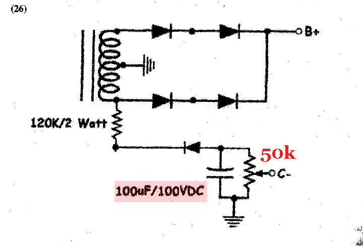
Garnet Bias Voltage Circuit Made Variable
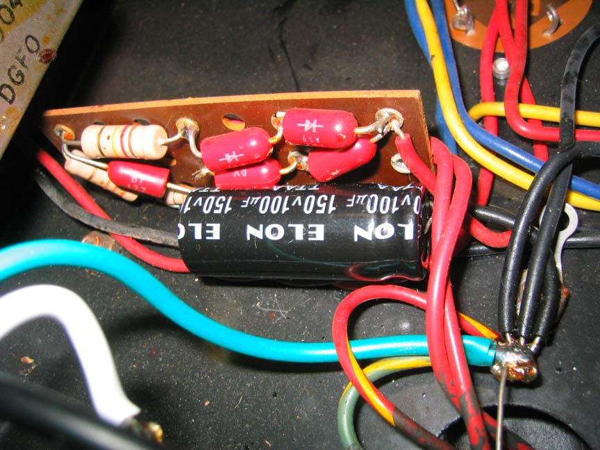
Early-era Garnet Bias board