Bias-Modulating "Tremolo" Circuits
JC Maillet (c) 2003, 2004, 2008
originally posted 11/19/03
Here's a collection of Bias-modulating "Tremolo" circuits which I use for retro-fitting common class-AB guitar amplifiers, circuits which are mostly based around the high gain 12ax7 dual Triode. Fender amps made prior to 1963 carried this type of Bias-based Tremolo circuit - but it was labelled "Vibrato" on Fender amplifiers. To most people I guess Vibrato implies presence of pitch-shifting, but pitch-shfting doesn't manifest itself in either the bias-modulating circuits or the photo-cell circuits - it's just Amplitude Modulaion (AM) ... Garnet tubes amps containing Tremolo effect also used this principle, as well as many Traynor amps (except for YGL-3 and YRM-1 which are photocell based) which correctly labelled the effect "Tremolo" ... some players find the bias modulating circuits more musical, some don't ...
From a modster's point of view there's a subsiduary advantage to modifying photocell/preamp based Tremolo circuits into this older type of circuit arrangement in that it frees up the preamp from at least this one constraint leaving things more open to mods or re-designs ... for example, a common old-school "upper" mod to a 2-channel Fender Silverface Reverb amp consisted of simply disconnecting the feed from the preamp leg in channel-2 to the Vibrato pot in order to decrease signal loading (resulting attenuation) at that point ... In the olden days, this mod meant loosing Tremolo function - but not if you know how to convert to output-bias Trem ... as an example, at this point I could wire in a Tweed Bassman preamp circuit and not have to worry about how the Photocell trem feed would fit into all that ...etc.
Note: each circuit presented here is recommended for use with a particular type of power tube load and sufficient/necessary voltage swing - the circuit needs to match the input swing requirements of the tube to the output of the Tremolo circuit ... these particular Tremolo circuits are derived from amplifier examples that seem design-stable ... (*) it should be said that one way of exploring the pairing of the Tremolo circuit with your amp is by varying the Bias of the power tubes and noting how much the Tremolo effect has on the amp at full intensity - when you've settled on a level you like take a measurement of the bias current and compare it to what you would normally have set it at, they should not be too far off in value for a good Trem circuit match to your output stage ...
Important Adjustment Principle: if the power tubes turn red at full intensity then the bias control needs to be adjusted for less idle current (more negative bias voltage), conversely if the Tremolo effect has little effect at full Intensity then the bias needs to be adjusted for more idle current (less negative bias voltage) ... the following circuits have all been borrowed from Fender and Traynor guitar amplifier examples, especially for their design stability over years of production.
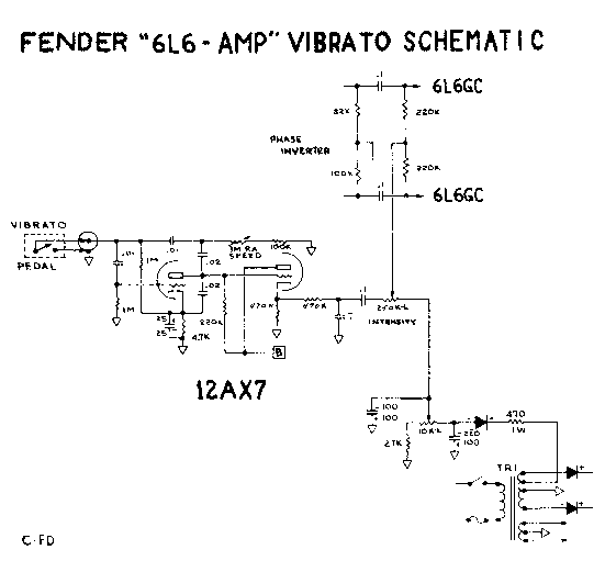
Tremolo Circuit for 6L6GC powered amps
This circuit is derived from the last 6L6 Tremolo circuit version, the 1959 6G16 Brownface Vibroverb ... it was unchanged till the next generation in1963, so it may be considered a most stable design compared to shorter-lived variants ...
 |
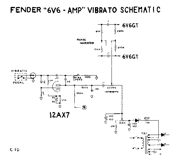
Tremolo Circuit for 6v6 powered amps
... this circuit is derived from the '64 Princeton which CBS later kept, a longstanding circuit in the Fender history book ... the oscillator tube drives the power tubes directly without a Cathode-Follower buffer stage ...
 |
'94 Custom Shop Tremolo Circuits
Used in the '63 Vibroverb and Vibrolux Reverb re-issue Amplifiers
... in this circuit the Tremolo Speed is given a greater Speed range and better amplitude stabilization due to the introduction of Negative Feedback from the output of the follower stage back to the oscillator loop input ... it's a modern variation on the old style ...
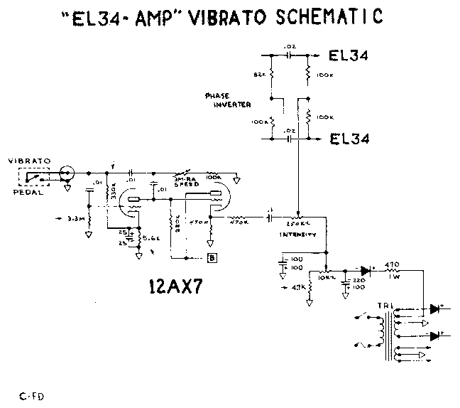
Tremolo Circuit for EL34 powered amps
... this circuit is derived from the '69 Traynor Custom Reverb (YSR-1) amplifier which runs on EL34's ... the circuit is very similar to a Fender circuit save a few component changes ... I use this Tremolo circuit in a '69 Super Reverb running on EL34 (per Ken Fischer) - unbelievably fantastic !!
 |
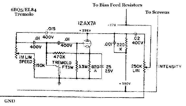
Tremolo Circuit for EL84 powered amps
This one is derived from the Traynor Guitar-Mate (YGM4-3) amplifier which runs on EL84's ... someone asked me if it would work in a Fender Princeton converted to EL84's - it should, you try it out and tell me ...
 |
Note 1 There's an extra stage of capacitive filtering in the bias circuit examples shown above, this easy upgrade may help bring down output stage hum a little - a technique that was routinely used in passive-biased HiFi tube amplifiers ... in some amps using such high capacitor values in both positions may load the circuit down too much - in which case try smaller values like 47uF in the first and 22uF on the sweeper position ... the original schematic for your amp will guide you although it's good to remember that some amp manufacturers at times had their bias filter caps under-valued ... the bias circuit capacitor values drawn above are extreme in value to give an idea, taking the circuit a little longer to charge up also, but they should work ok with most bias circuit feeders ... this bias circuit filtering arrangement is meant to provide a more "solid" bias voltage to your output stage, ie., with much less AC ripple riding on it ...
Note 2 These older types of Tremolo circuits eventually got replaced by a photo-cell arrangement after becoming a customer relation's nightmare for tube amp companies ... if a class-AB output stage is improperly biased then the bias modulating Tremolo circuit can either have little effect on the output stage or it can drive the power tubes into meltdown when the "intensity" control is maxed ... this may be a reason why some amp manufacturers insist that people NOT modify or install variable bias in their fixed-bias amps (but that's another issue) ... if your amp starts acting funny when any of these Tremolo circuits are operating then it's time to either re-bias the power tubes or replace them with a new set and bias ...
Note 3 Using a Matched set of power tubes helps elliminate power supply feedthrough that can potentially turn into a form of LFO pumping in your speakers ... it starts from the Tremolo circuit, drives the power tubes vertically at first, manifests through the output circuit through widely varying Plate currents, loading the power supply on half-cycles, feeding back into the preamp through its supply feed, and with preamp bass control maxed then feds back to the output thus driving the power tubes into "Assymetric" LFO mode and pumping the speakers (if it starts to happen it will seem very weird at first) ... using reasonably matched power tubes and employing the same power supply feeds as noted in the above schematics typically guarantees problem-free operation following proper power tube biasing ...
Here's another example of tube bias modulation, this time taking place on a triode in the front of the preamp of a Valco 6166 Single-Ended amplifier (er, ... notice the absence of NFB on the output transformer - yummy ! ...). What makes this Tremolo circuit unique in this amp is the appearance of "differential" coupled cathode circuitry, with one input seeing audio and the other an LFO signal - tres cool :)~
This schematic was generously provided by John Cunningham ... Thank-you !!
viva Analog /// jc -> lynx.net


