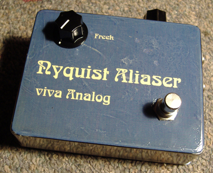
"Nyquist Aliaser"
Under-Samplig Project
JC Maillet (c) 2006
 |
While mulling over the idea of producing a S/H circuit that could run on a single 9v supply I stumbled on a simple circuit that can perform under-sampling sidebands as described by the Nyquist Sampling Theorem ... for those who don't know, sampling is the first step in converting analogue signals to digital - the next step consists of according the output fixed levels somehow encoded to a discrete vertical scale ... I'm not interested in the second part, we're staying in the analogue domain ...
The sampling theorem states that aliasing of a fixed bandwidth signal spectrum will produce frequency overlapping if the sampling frequency isn't at least twice that of the highest frequency component in the spectrum of the source material ... well, since lots of interesting music circuits act contrary to conventional fidelity principles the idea came to me of exploring what happens when you go against the principle and bring down those side bands into the audible spectrum ... personally I've never heard of this principle used as an effect so I thought I'd try it out ...
If you're into Ring-Mods and Multiplying Octavers you may like the sound of this thing ... when the sampling frequency is set high enough chords come out sounding not so screwed up as they do with the two other modulator category circuits ... by varying the Sampling Freek knob we indirectly control the amount of wave-screwing that occurs ...
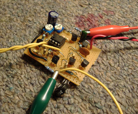 |
A few notes about this circuit:
(i) the 10k trimmer sets the reference voltage on the oscillator circuit - varying this voltage sets the frequency range ... Charlie Barth (www.moosapotumus.com) found a way to envelope-modulate this reference, that's pretty cool !
(ii) the 100k trimmer on the second op-amp is there because my simulator showed I might not get a tall enough sampling spike out of one op-amp alone ... in my prototype this didn't turn out to be true - I guess it depends on a number of factors - jFET and op-amp characteristics primairily ... nonetheless, it doesn't do any harm as is and it may be useful for some depending on what active componentes you use ...
(iii) the 10k gain trimmer sets the Emitter bias on the Bipolar transistor in the FET/Bipolar Darlington pair ... it's important to set this at the right value for the sampler to workľ ... interestingly, this trimmer also has an effect on clock feedthrough going into the sampler - in fact, a nulling point occurs within the useful gain range - sister luck !
(iv) I provided simple passive isolation between the two parts of the circuit to minimize clock feeding through the rails ... I used 121ohm resistors between both grounds and rails, filtered by a 47uF cap ... I tried 2200uF and it didn't seem to make a huge difference - but these are just preliminary results anyway ... I also tried hooking things both ways, battery to clock first and then audio after the filter, and vice-versa ... I settled on the later, seemed to be a little better this way ... with gain trimmer properly adjusted I get reasonably low clock feedthrough - enough to make the effect quite useable ... this makes some sense since the gain trimmer adjusts the DC of the sampling channel, and since the clock pulse doesn't go fully from ground to rail there's a voltage play possible that allows the gate device to turn on and off adequately while not going too far to produce feedthrough ... so, the bias isolation and jFET characteristics in the LFO have to be chosen so that clock feedthrough cancellation can be maxed ...
(v) sticking an input cap is not necessary here - unless you are preceding this pedal with another that puts out non-zero DC (same thing with most tube amps) ... a good reason not to put a cap here because it could contribute to foot-switch popping as well, while the direct input case doesn't ... this circuit as I've drawn it does not pop at all ... notice the signal encounters only one signal cap in total as it swims to the output - the signal path is DC-coupled up until then ... surely, making the signal go through only one stage of capacitance total must be a way at aiming for top transients ... yep, some reflections on gizmo land design for FI-ness ...
\\\ CLIP ///
(c) 2006 JC Maillet
Wurlitzer 270 >> Nyquist Aliaser >> Korg D1600
... and now, the long version for my late-night engineering amigo Jim :
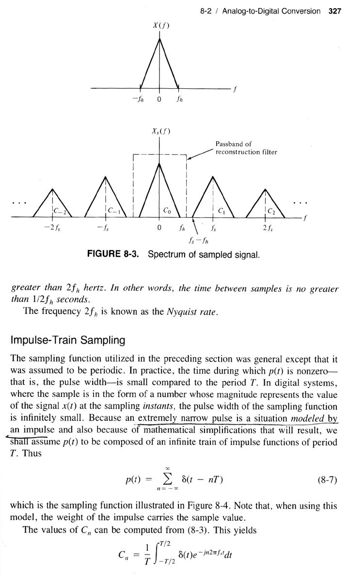
From a spectral point of view the Sampling Theorem states that input band energy is replicated along the frequency axis at multiples of the sampling frequency - this assumes ideal (clean) sampling operation ... anyway, in particular this states that a replica at n=1 exists which means that unlike Ring-Mod circuits you do get strong fundamental feedthrough using sampling ... in a way this helps keep things musically rellevant ... the first clip sweeps the clock frequency from ultra-sonic down to around 50Hz to show how the original signal comes through at the output - that's until the sampling frequency arrives within range of the signal frequencies where the output sort of dies, then as it crosses below you start hearing RM type mayhem ... "below the fundamental" is an area not well described by theory ... you can play one note and animate the shit out of it with the Sampling "Freek" knob - following all that with delay pedal (!) ... btw, under-Sampling and Decimation (bit crushing) have two different functions on signal - not to be confused ...
Sampling Principles
Excerpts taken from :
"Signals and Systems: Continuous and Discrete" 2nd edition
by Roger E. Ziemer, William H. Tranter, D. Ronald Fannin
 |
 |
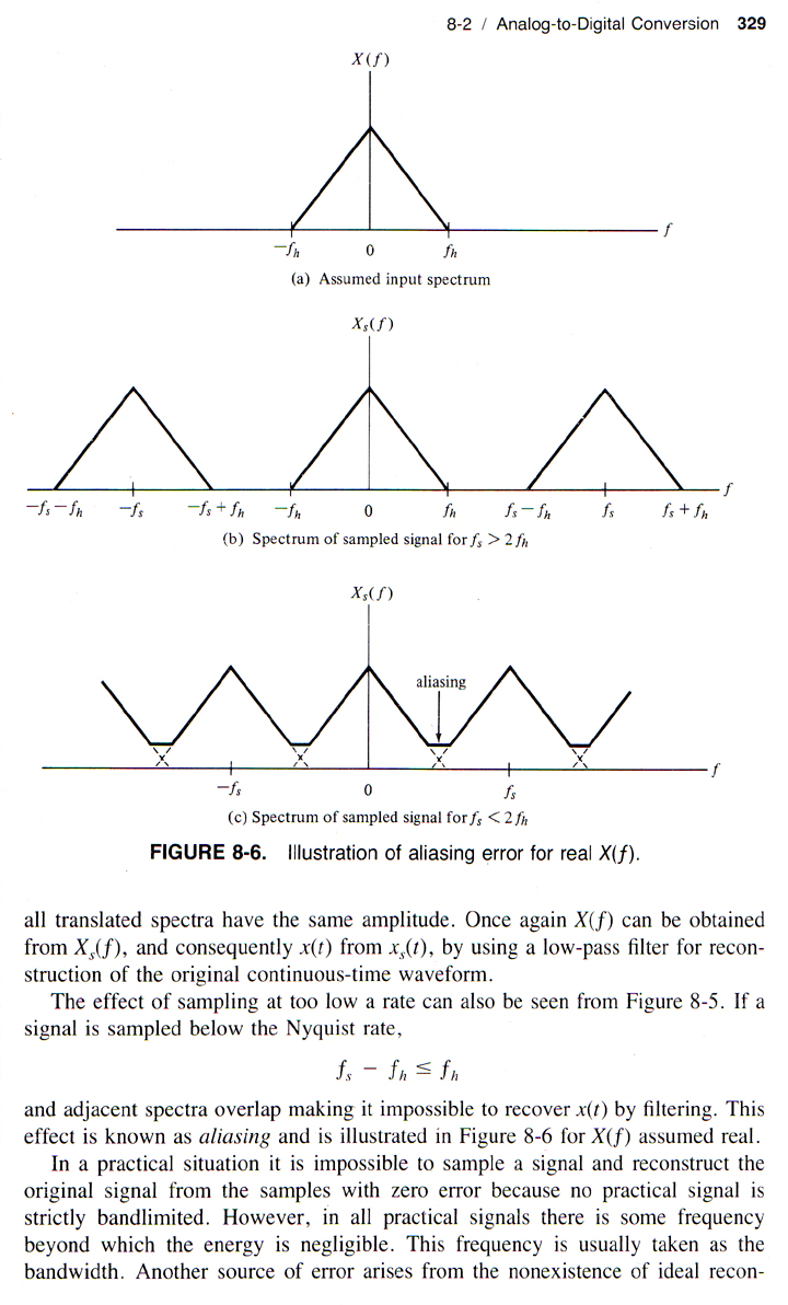 |
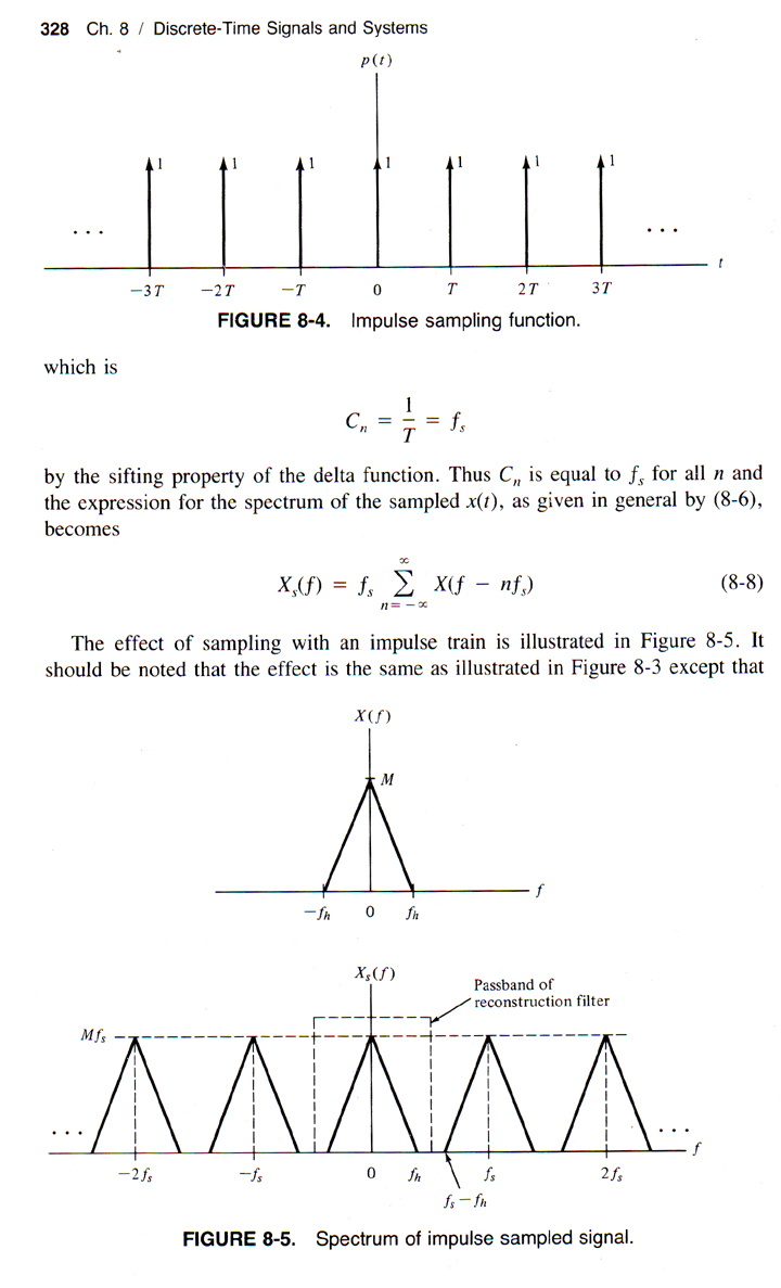
These pages demonstrate the standard theoretical model for aliasing ... it should be noted that the sampling theory as described above makes a couple of important assumptions: (i) the input signal is bandwidth limited, (ii) the sampling clock pulse width is zero, ideally an impulse ... the first condition is always satisfied when processing musical instrument signals (easily) and the second means that a narrow pulse LFO needs to be used if the theorem is to be well approximated by real circuitry ... this was a personal target for me, that's all ... if the clock pulse doesn't have particularly narrow width then the principle works the same but not as "cleanly" ... I'm not suggesting one is better "sonically" than the other - it's all experimental at this point ... looking at Fig 8.6 note that the input signal X(f) being preserved in it's original location aside from the sidebands produced/added by the sampling operation ... in other words, the input signal comes out undistorted and in no way frequency shifted within the total mix of sidebands ... unlike what a Ring-Modulator (multiplier) circuit produces ...