posted (4/'00) updated (8/'01)&(11/'09)
Dedicated to Barry Gilbert
A while back I became interested in cloning the EMS VCS3 synthesizer that Pink Floyd and many other bands used to produce amazing electronic-machine sounds - in reality it's an audio-range "analog computer" ... in the process I became acquainted with Jurgen Haible, a master analog synth clone-meister, who himself was cloning the VCS3 ( Jurgen's page ) ... among the many retrofits he came up with for this was a more modern implementation of the EMS Ring Modulator circuit, based around a LM1496 multiplier chip, with much less offset problems than the original discrete EMS design
I tied the inputs together and augmented the whole thing with an op-amp based in/out mixing circuit - a typical strategy for producing "squaring" ...the idea is that by buffering the input and output circuits of the "tied" EMS Ring Modulator (Multiplier) circuit you can arrive at a circuit that will blend in progressive amounts of pure 2nd Harmonic ranging from 0% to 100% in a linear manner
At around 5-10% Mix you get a growly tube amp type effect that fakishly sounds like a Fender Bassman ... it warms up basses pretty good too ... in Octavia mode (full mix) you get deep ring-moddy sounds that are unlike the typical starved-pair configurations ... reason why this Octavia sound is unlike a full-wave rectifier based circuit because it's based on analog multiplication of signal ... for sinewaves we get sin(x)*sin(x)=1/2(1+cos(2x)) and not the transfer function of full wave rectification which yields a f(x)=|x| function ... you figure out the Fourier series for this and will see why you get other significant terms other than just the second harmonic ...
This is a simplified version to the circuit I first released in fall of '00 ... I took out the emitter followers of the EMS Clone input circuit because I found that their lower drive levels had litle to do with the purity of the octave component ...
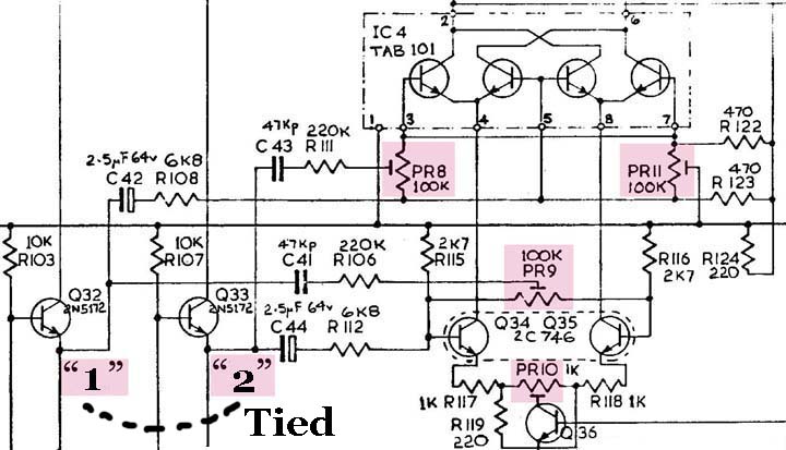
Consider that the input op-amp in the Harmonic Multiplier circuit is serving as a (better) buffer to the four R-C paths (labelled A-B-C-D in my schematic), thus replacing two emitter follower stages that were driving two R-C branches each - the R-C paths operate in two groups of two if you compare them to the original EMS circuit ... notice that the first op-amp also works as buffer to the linear mixer, that's three birds with one op-amp ... in the EMS version of the circuit the multiplier section is nulled by sending signal to one input group (two R-C paths) at a time ... in my schematic the two input paths correspond to path groups B,D and A,C - to be clear one path group is left open during the nulling of the other ... these input path groups correspond to input "1" and "2" in the re-labelled EMS schematic shown below, the instructions refer to them as inputs A and B for the original Ring Modulator - the important thing to remember is which set of R-C input paths and preset trimmers go together... btw, in the HM schematic I'm drawing disconnects (...) on the side of the multiplier - it makes no difference which end of a circuit "branch" is disconnected - the idea is to avoid feeding signal from the op-amp to the multiplier through two R-C paths while the other two are used for nulling ...
As far as debugging is concerned don't forget to raise the bottom rail to -7.5v from -9v (that's what the two silicon diodes are there for) ... any generic small-signal transistor will work as a current source in the circuit - ie., 2n3904, 2n2222, 2n5210, 2n5089, etc ... remember to be be careful not to hit the multiplier with too much signal they blow easy under too much stress - I keep spare LM1496's for this reason ... therefore I'd suggest also going easy with the amplifier gains - bring them up high enough that you get good S/N with your instrument, but not too high that you hear clipping with lots of Pickup signal ... try not to forget this when you drive another circuit into the Harmonic Multiplier
To null-out each side of the multiplier you'll need to feed a constant tone to only one pair of R-C paths at a time (through the input amplifier) ... I've used a Theremin as a signal test source - as long as it's a "cleanish" waveform you'll hear the partials move with the trimmers ... do the same on the other set of input - when you're done, hook up all R-C paths to the multiplier and don't touch the trimpots again ... by nulling out the harmonic side-terms you'll end up with an octaver circuit that exhibits very little fundamental and 4th harmonic feedthrough ... so, in essence, producing a quite pure analog octave when processing a sinewave "test" input - and then producing sharper sounding sideband products when processing a more complex signal ... very musical and unique - the low-mix (Bassman Sim) mode has shown itself handy in the studio for slightly unmatching doubling tracks - check it out !
viva Analog /// jc CHEZ lynx.net