viva Analog Univibe+
all pics/drawings (c) 1996 - 2009 JC Maillet
 |
 |
 |
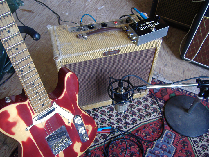
Univibe+ built for Steve Woods, Long Beach Ca.
Although some people have claimed to reproduce the Univibe circuit down to a T my approach has been to start from the basic topology and modernize for improved performance. Below is a synopsis of different routes I've taken.
The Ultimate Phasor /// Maximizing Univibe Performance
Of the several different approaches to producing electronic phase shifting the Light Dependent Resistor (LDR) approach is IMO by far the best all around way of doing it, that's provided you can find photo-cell assemblies that have an extended range and speed if a high swirl speed is desired. In this case there is no low-headroom (distortion) problems like with OTA and FET transistor based phasor circuits. And unlike Varistor based circuits the LDR approach affords no serious noise leakage from the control circuit to the audio path save for a slight rise in 1/f noise when the cell is strongly lit. Otherwise, the LDR is linear like a normal fixed resistor, very quiet and has as wide and better controlled resistance range than so-called "matched" FET devices. The only possible drawback versus using FET devices could be in tracking the LFO at high speeds, but we find that fast cells do the job well into the "pre-warble" range anyway - so nothing lost there really ... IMO, opto-cells rule when it comes to building quality phasors
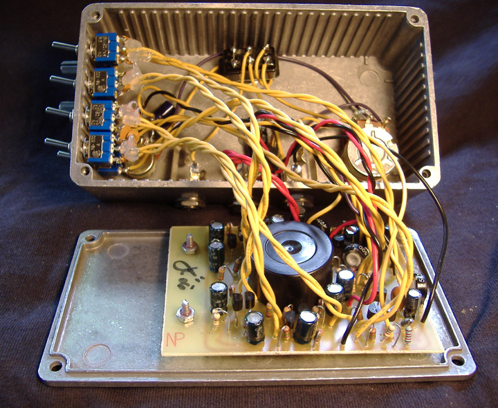
My concept of a modded/optimized Univibe style Shifty involves: (i) replacing of the stock low-headroom Univibe front-end by a higher headroom variable gain preamp, (ii) improving the bulb bias and control circuitry, (iii) maintaining the stock Univibe signal path save for having the ability to toggle between stock Vibe caps and Resly-Tone ones ... also, (iV) an extrenal LED Rate Indicator runs in sync with the oscillator, and also dims along with the Intensity control ... the jFET preamp provides a gain boost factor of up to x5, and a Presence control sets optimum amounts of treble output since the FET front end naturally boosts the treble slightly ... although it has more headroom than the stock Univibe front-end at the same time it can give a pleasant FET-OD when played hard, with a smooth and gradual transition in between clean and dirty ... very compatible with tube amps
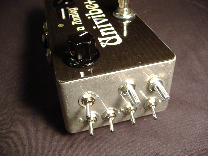
The Resly-Tone filter caps (*) follow a different ordering of values than the stock Univibe ones - both produce cool sounds on their own but their combination also gives great hybrid responses - double bonus !! ... the mixing of these two sets of values turned out to provide (IMO) the best alternatives of anything I've tried, giving 16 moderately different shades in total ... the center switch on the side selects between Pitch-shifting Vibrato and Phasing modes and the two knobs next to it control Volume and Presence ...
\\\ CLIP ///
(c) 2006 JC Maillet
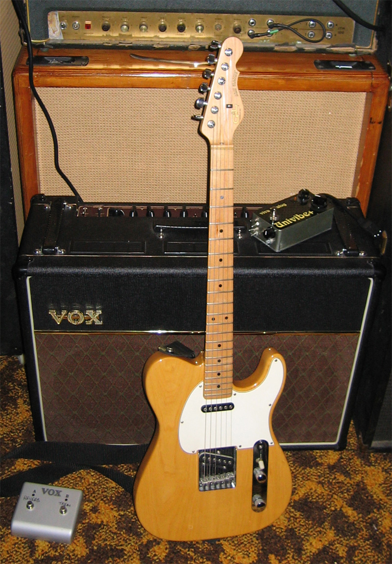
Mexi Tele >> Univibe+ >> Tweed Princeton >> SE3600>> Korg D1600
 |
 |
 |
Early "Variational" Prototypes
 |
The Vibe on the left I built for blues/fusion artist Tim Butler in Winnipeg - it has variable mixing ratio knobs on the back ... the one on the right is my proto-unit which has the variability knobs on top ... a test unit that I gig with
Unicord Univibe Mods ('02)
All Schematics and Mods Copyright (c) JC Maillet '96 - '04
 |
About The Stock Univibe Circuit
The stock Univibe circuit can simply be described as a low-headroom preamp feeding a cascaded quad of (lossy) unity-gain all-pass circuits - with a passive network blending pre-direct and vibrato signals to produce phasing, while the chorus output is taken directly from the Vibrato side with no pre-direct mixing ... the lossyness of the class-A Univibe stage is due to the way in-phase and anti-phase signals are combined and load each other before going to the next phasor stages ... this is in sharp contrast to op-amp based all-pass circuits which exhibit perfectly flat magnitude response which is due to the lack of network loading taking place there ...
the signal path of the Univibe is single-ended, or "true" class-A to some, throughout which is responsible for the subtle dynamic feel of the circuit ... to do its thing the all-pass filters mix in-phase and anti-phase signals through a light-variable RC network ... the "in-phase" legs include a photocell who'se variable resistance is light controlled and in turn sets the amount of differential bandwidth cancellation between in-phase and out-of-phase signal components filtering to the next stage, and so on ... the resistance range of the photocells will largely determine the ability of this phasor architecture to sweep the response curves with acceptable range across the audio frequency band ... for one, making sure the bulb turns On and OFF at the right levels is crucial in reaching this target ... original Univibes are known for their inconsistency, certainly some of the inherent variability present in the circuit is responsible for this - especially in the bulb driver circuit ...
Unlike many modern "studio" Phasors the capacitors that set the phase-shift cutoff frequencies in the all-pass filter stages are staggered in values instead of being set identical to one-another - this has the effect of applying different amounts of phase shift at different frequencies for any given amount of cell resistance (or bulb intensity), it also produces some low-end pulsing which is a trademark of the circuit ... simple RC analysis shows that the caps, which lie about a decade apart in two pair sets (0.15 = roughly 0.022 x10 and 4700pF = 10 x 470p), have the effect of providing linear phase shift over two decades of frequency for each pair ... the principle behind the "octave" cap ratios can be exported to other phasors like the EH Small-Stone, MXR Phase45 or any Op-Amp/OTA based phasors to produce variations that are somewhat similar sounding to the Univibe ... to be clear, I'm not necessarily implying using the same cap values but rather using the "decade" cap ratio ... in the classic version of the circuit the result is a pitch shifter who's Bode transfer curve set is characterized by an un-even magnitude response that turns into a notch filter when the bulb is shining bright while the phase response ...
The unique current mode phase-shifting oscillator and slow turn-off character of the bulb-driver circuit defines the uneven LFO aspect of the Univibe which is very unlike op-amp based triangle waveform generators, this is also a contributing factor in the uniqueness of the Univibe effect ... Between the class-A feel of the signal path, the staggered cap values in the filter stages and the uneven sway of the bulb oscillator and driver makes the Univibe experience nearly impossible to duplicate completely through other circuit means ...
Cloning the Stock Circuit (c) '98
 |
Cloning the Univibe circuit involves duplicating the salient audio mechanisms with modern parts ... keeping in mind that original Univibes, to a degree, varied in response from one another ... there are three important areas in the circuit that need to be respected to attain an acceptable overall approximation to the effect : (i) the signal path architecture and "key" cap values in the shifting stages, (ii) photocell ranges and (iii) the oscillator and bulb driver characteristics ... since the original power supply exhibited a little hum feedthrough and doesn't play an interactive "loading" role with the signal path we can replace it by a modern no-hum equivalent - the original Unicord circuit operated at 24vdc but it can be operated with success down to 9vdc (not as good sounding), so there is an acceptable element of variability at the supply level ... presently I use a 24vdc wall-wart and 7824 regulator - the bulb driver and oscillator runs directly off the wall-wart (around 29vdc, which provides the oscillator with more gain) and the signal path is fed by the regulator ... in the early days I used 15v and 18v regulators to power the signal path ...
Recommended Off-board Wiring and Component Layout
 |
About the Bulb and Bulb Driver circuit
Some of the recently made cells from Silonex seem to have the right light sensitivity and response times - but I haven't tried them yet ... what seems to work best is sticking to a fairly stock version of the Univibe Oscillator and Bulb Driver circuit and using those precious cells if you can find them ... currently, I use a 12v/25mA Radio Shack bulb which has good turn-off time ... Note: because the filament is typicaly strait inside the glass bulb, there can be dark sides on opposite sides of the filament hooks ... you simply need to squeeze the photocells tighter together, 2 per bulb side, to avoid having the dark zones hitting the cell surfaces ... or use two bulbs wired in series - one per pair of cells ...
 |
From studying the Vibe circuit it seems apparent to me that one area highly sensitive to circuit variations is the Bulb Driver circuit ... because it is unlikely we'll ever know the exact specs of the bulb used in the Univibe and to account for circuit component variations (esp. the drive transistor) I have devised a method of making the driver circuit variable so that exact turn-on and turn-off points can be dialed in with the use of two trimmers ... one for Gain and one for Offset ...
 |
My modded Univibe Bulb Driver circuit incorporates several changes which allows for use of modern parts to perform adequate functions ... (i) is the use of commonly obtained bulbs (25mA - 40 mA), (ii) a Darlington pair using 2n3904 NPN transistors to drive the bulb and (iii) an "Offset Adjust" trimmer which allows for a vertical displacement of the bulb current "Average" ... as long as you choose a bulb that isn't rated for very high current it should work, but just the same the original circuit has a tendency to make the driver device hot (which is why a 47k resistor lay at the Base of the original device) - a Darlington pair helps things a little bit without altering the response of the circuit ... the most likely "variablility" culprit in the whole affair would involve the turn-ON/turn-OFF threshold of the bulb driver - by providing an Offset control to the driver circuit both the driver Gain and Offset adjustment trimmers can be tweaked so that the exact amount of dark-time can be set aganst the maximum brightness of the bulb - this will provide a desired response from the circuit regardless of the bulb your choose (as long as it's in the ballpark) ...
 |
This plot shows how the Gain Adjust trimmer alone would affect the bulb brightness AND darkness throughout the oscillator cycle while the Offset adjust would be used to remedy for an overly long darkness period at maximum LFO signal settings ... in reality the Offset adjust also affects gain a little but in practice both are trimmed conjointly in an iterative way to produce a desired response against supply voltage levels and exact bulb and transistors used ... finished are the hassles associated with finding the exact Bulb to get the thing working right !
** "Univibe-in-a-CryBaby" Clones ** ('96)
 |
 |
 |
 |
 |
Unicord Univibe Manual
 |
Original Univibe Modification Ideas
External LED Speed/Intensity Monitor
Mods Copyright (c) JC Maillet 1996, 1998, 2002, 2008
A useful mod is the inclusion of an LED in the bulb circuit ... since my pypass switch doesn't kill the oscillator (as in the original) this external Speed monitor is running as long as power is supplied to the pedal and the Intensity control is turned up ... if the LED is well matched to the current draw of the bulb driver than no parallel resistance need be included across the LED - when balanced the LED should also mimmic the "Intensity" control fairly well as it is reduced ... btw, the LED doesn't rob enough voltage to the bulb to affect the basic operation of the bulb driver circuit ...
 |
Univibe Bulb Driver Schematic with Darlington and Offset Adjust Mods ('94)
The Darlington bulb driver presents a smaller current load to the Intensity circuit (two large caps split by a 50k pot) and allows a little more signal to drive the bulb driver at really low speeds - subtle ... the Offset Adjust mod on the Bulb driver allows to dial in a bulb of wide spec range so the Vibe has maximum effect depth at low speeds ...
This is exactly how I wire the Univibe+ signal path except for the Drive trimmer mod - I keep the stock 4k7 resistors ... trimmers are an option when someone wants to extend response depth - something to try in a big-box prototype ... the mu-stage is designed for low max-gain (x5), it has a slight distortion when pushed hard which jives well with tube amps ... the Presence control allows the user to dial in just the right amount of top end ...
Univibe PSU and Oscillator Mods
I recommend powering the Univibe clone with a 24vdc@350mA AC adapter ... the oscillator/bulb circuits run off the wall-wart output and a 7824 regulator (with 470uF output cap) is used to run the Signal Path at stock voltages - the signal path does sound a bit better running at full (stock) voltage ... because the whole circuit doesn't pull much more than 50mA, depending on which bulb you use, it means the voltage coming out of the wall-wart will be close to 30vdc [note: since the wall-wart is rated as providing 24vdc when pulling 350mA (out of it) and we're pulling 1/7 max of that nominal load current we should expect more output voltage] ... this 29vdc gives the oscillator more output at slow speeds and therefore helps to produce a stronger effect at low speeds ... the 2M2 Bias Feed resistor in the Oscillator part can be increased to 5Meg or more to provide an extended low Speed range - this is very useful for doing things like Floyd's "Breath", etc ... I also reduce the resistors in series with the dual speed pot to bring the top range up - I use 1k2 instead of 4k7 limiting resistor - less limit = higher top speed ... these mods work together to max out Vibe performance...
Univibe Speed Controller Mods
For some time now I've been messin' with a simple single-pot opto control circuit that replaces the dual pot and matches well with the limited (2/3 rotation) pot travel in a cry-baby against the speed range of the Univibe oscillator ... it uses a standard 100k wah pot for control - I will be drawing this up shortly ...
Univibe Output Stage Mods
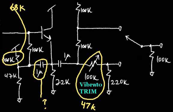 |
The 1uF Boot-strap cap in the last stage can be omitted - in my own builds I leave it out, that's why it's not included in my original layout ... you may wish to experiment with having that cap in there or not, some people think leaving it out makes the Vibe sound a hair better ... in my redrawn schematic I have a 100k resistor instead of 68k in the bias circuit of that stage - no biggie, using the (stock) 68k value increases the bias voltage and allows for a little more headroom, but the difference is negligeable and not needed really since the signal path operates near unity gain and signals rarely exceed 200mV - using 100k brings the noise down a hair in that stage without imparting a noticeable loss in headroom ... the output 47k Vibrato output can be replaced by a 100k trimmer which allows for easy under/over tweaking of the Vibrato mode output signal ...
Sent by Steve Little of Ottawa Ontario
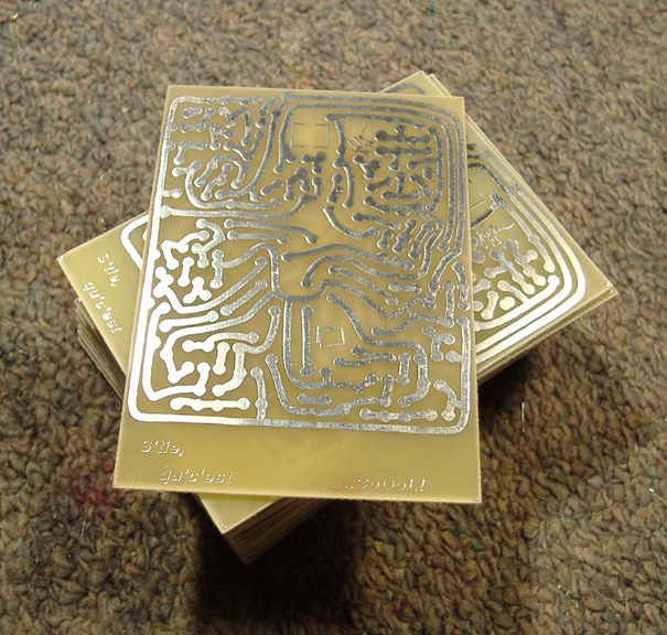
Original "PCB boards" for the Univibe+ are Currently Available
$20US/board, shipping included to US/Canada - Europe and Asia please add $10US
(Instructions are included on this Webpage)
 |
The FORUM-Vibe Project
 |
Brad Burt (aka Red House) is a maker of extremely fine Univibe clones - we've been corresponding over the years and have had interesting discussions concerning this circuit ... ForumVibe is a compendium of mods and cloning ideas that Brad distilled from public discussion ... several interesting options are provided including the author's preferred ones - Wima and Panasonic caps anyone ?! great work !
jc AT lynx DOT net