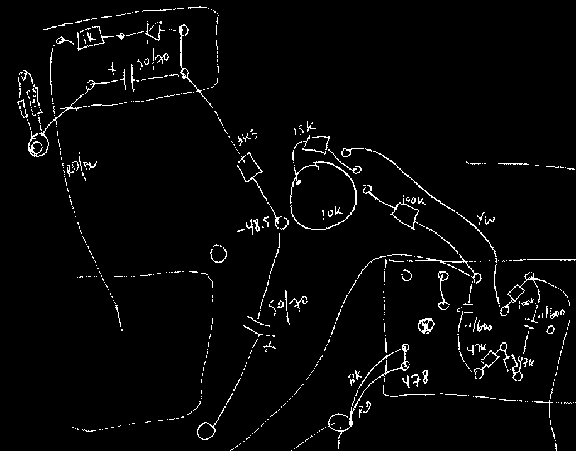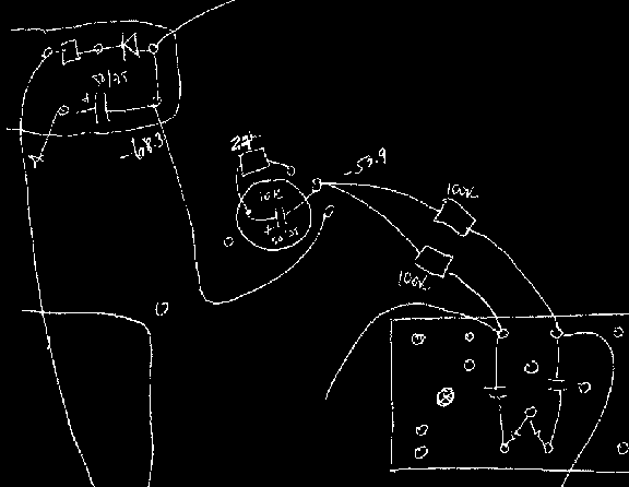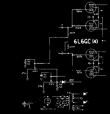
... around 1968, CBS engineers thought they'd introduce a differential bias arrangement on the output stage as means of cancelling overall power tube plate-spec mismatch by pairing the grid circuits with a tunable resistive divider circuit ... a nice idea in theory, in practice it doesn't work and most techs replace that circuit by an earlier true-and-tried Fender equivalent circuits ... more importantly the common-mode bias (absolute voltage levels) cannot be adjusted ... this means the amp cannot be properly biased as in the earlier Fender stock circuit (the circuit most tube amps use anyway) ... especially in the case where you mod the signal path of your Fender Silverface amp for heightened tone you'll want to alter this circuit so the power tubes can properly biased (this is crucial in my opinion) ... the schematic below shows what you'd find in a typical 70's Fender Super Reverb Amplifier ...


... in the revised circuit, notice the addition of a filter cap on the sweeper of the bias pot ... this is an extra that I add as part of my overall "hum ellimination" strategy ... I make use of this addition on a systematic basis, brings hum down quite a bit sometimes (one of the "negators" I use for elliminating hum completely in the end) and it doesn't stress the bias circuit in any way when using reasonable values (50uF/75v) ... the addition of an AC ground in the circuit could perhaps bring about the possibility of making things sound stiffer somewhere in the output stage but I can never detect any difference aside from lower hum at idle, the grid bias resistor values (usually either 100k or 220k) dominate over the drive impedance anyway ...
An important point also is the choice for a replacement resistor on the potentiometer divider circuit - here I show a value of 27k-Ohm; this gives a wide enough adjustment range but at times this value may be different depending on the volatge levels of the Power tranny ... check Fender schematics for values and ideas ...

Pictured here is a dual bias system, I tried it a number of years ago to test out the possibility of making good but unbalanced tubes behave like a matched set ... after doing some incremental 2-D sweeps on several pairs of tubes I fast realised there's no way you can get close tonally and dynamically to what you get with a pair/quad set of dynamically and statically balanced tubes ... after all, differential balancing is the mother of tweaking in the audio world; what you can do at home in your spare time is something that would be very costly in factory ...