Getting rid of Self-HUM in guitar tube amps
JC Maillet (c) 2004
posted 4/13/04
One can interpret early guitar tube amp architectures as examples of "mixed-signal" analog systems ... there we find the presence of up to three types of signals occupying the same platform: (i) signal frequencies from the guitar (ie. above 100-Hz or so), (ii) LFO signals (less than 5Hz) from the Tremolo circuit and (iii) 60-Hz or related hum coming from the power supply and filament circuit (a fixed frequency of 60-Hz and possibly its harmonics such as 120-Hz). Indeed, we're dealing with a mixed-signal system involving three frequency ranges of AC energy. Old vintage equipment is often synonymous with HUM and musicians have been forced to accept this as part of the technology. As it turns out, with proper recognition of the basic principles and through simple execution it is possible to pretty much eliminate all instances of hum in any old tube amp !
Electro-Magnetic principles at play ...
Hum feedthrough from the tube amp's power supply to the main AC signal path generally occurs by way of two basic mechanisms : (i) through Electro-magnetic Induction and, (ii) through Shared Impedances (Ground Loops). Electromagnetic Induction, the basis of operation for Transformers, operates on a principle of distance and orientation whereas Shared Impedances occur from using the amplifier chassis as a common conductor.
In a standard design tube amp you'll notice the power supply lies at one end of the chassis while the sensitive input side of the signal path lies at the other end - there are two reasons for this choice, namely to minimize the effects of Ground Sharing and Induction which are distance related. The magnetic field generated by the power tranny is one example, we can also concentrate on other aspects of amplifier hum which aren't "fixed".
Engineering techniques invariably involve making compromises, eg. presence of HUM against overall ease of manufacturing, so that at home one can take extra steps to maximize hum rejection in otherwise well-built amplifiers. By observing every possible "injection" mechanism and making efforts to minimize each one can the overall hum index of a tube amp be brought down to nil. What follows is a synopsis of the work I do to tube amps to eliminate the hum without resorting to costly DC filament supply blocks.
Eliminating Shared Impedances (Ground Loops)
The chassis of a common tube amp is typically used to provide a return path for the filter cap currents, as well as the filament circuit grounding as in some of the early Fender Tweed amps, and also, sometimes, for speaker grounding and Negative Feedback DC referencing (when present). There are several potential scenarios present here but the applied principles are the same.
Decoupling the Speaker Ground from the Chassis
In some amplifiers the return currents from the filter caps occurs through screws bolted to the chassis - these can sometimes lie close enough to the output speaker jacks so that a small amount of AC current feedthrough will occur if the jack is not chassis isolated. Because the ground connection of the speaker circuit to the audio circuit is only meant to provide DC voltage reference to the Feedback circuit and does not carry the principle speaker current. So, a ground isolating speaker jack can be used and then a wire installed going from the speaker jack ground to the Negative Feedback ground to maintain full circuit functionality while eliminating that potential hum component. This was brought to my attention a few years ago by an anonymous emailer (thx!)
Balancing the Filament Circuit w.r.t Chassis
To minimize filament AC feedthrough to the Cathode of the tubes both legs of the filament circuit may need symmetry adjustment with respect to the chassis potential (0-volt). As well, a pair of dedicated wires must run to the filament pins on the tubes, ie. the chassis should not be used on one side of the filament circuit as a means of avoiding the creation of a shared impedance scenario (also known as a Ground Loop scenario). A balancing "Hum-Adjust" network should then be installed as a means of tuning out imbalances between both legs of the filament winding on the power tranny. A 1watt 100-ohm wire wound pot is typically used for this.
If you find that the lowest hum position happens to be when this pot is turned completely to one side then a simple resistor can be used instead and the pot saved for another amp though I usually leave it in just in case things change with different tube sets.
 |
Reducing hum through better Wire Dress
The other means by which hum can creep into the audio path is through the principle of Electromagnetic Induction of AC signal energy. One principle states that when two wires are running in the same vicinity to one another, the one carrying an AC current will induce a similar AC current (in phase with the first) depending on the orientation and distance between the two wires. In particular, induced currents fall to the square of the distance between conductors and the are entirely reduced to zero if the wires are crossing at a 90 degree orientation to other (maximized when parallel). This implies that if two wires are virtually occupying the same space and are both carrying the same AC current but flowing in opposite direction together they should create a surrounding EM field that is practically zero everywhere in space. From these principles we can aim to take advantage of these ideas by dressing the filament wires to nearly elliminate all induction of AC 60hz energy from the filament wires into the most sensitive part of the signal path, ie. the wires leading to vacuum tube "input" grid terminals.
Minimizing stray EM fields from the Filament wiring
Some guitar amplifier makers, like Marshall, had their filament wiring hugging the chassis (Ground Plane) as a means of reducing the generation of an EM field around their filament wiring - many others, like Fender and Traynor, opted to have the filament wiring hanging up in the air away from the audio circuitry.
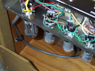 |
Photo source: Unknown ...
A common problem seen in some 70's Silverface Fender amps is a lack of tightning of the filament wires around each other - I often see this also in home-made projects, cf. "green wire pairs" in above photo. When you encounter this situation un-solder one of the four legs in a filament feed pair and give it an extra twist or two around the other filament wire so they are both very tight and straight around each other. Do this for each filament feed pair going between tube sockets but make sure you don't make them too tight that you can't pull them up away from the audio wires underneath. Having both wires occupying the same physical space (as much as is reasonably possible) will reduce the stray fields that constitute a principal source of induced 60-Hz noise in the audio wiring. Make sure that these filament wire pairs are all aligned in a straight line along the direction of the tube sockets in order to maximize orthogonality with signal wiring underneath.
Wire Orthogonality and Distancing
If you notice, the audio and filament wiring in 60's Fender amps vaguely run in a pseudo 90-degree direction to each other - this is no accident if you consider the EM Induction principle for AC signals. Often the wiring doesnt really run at a 90-degree angle at all, especially as it passes around the back of the tube sockets. Still, as the wires run away towards the board one can eliminate some AC induction by running the wires to the board orthogonally as much as possible. This is especially important of wires running to the input grid terminals on tubes ... Note As they come off the board all Signal wires should lie snug against the chassis surface which acts as a "field killing" noise shield. If there is any section of signal wiring that must run parallel to the filament wiring line it is a good idea to make that parallel section take place as far away as possible from the filament supply line.
 |
In some amplifiers, there may be wires that carries a hefty amount of hum which run along side "input" wiring - an example of this is the oscillator defeat feed in Fender photo-cell vibrato amplifiers - in some versions it runs right along the input wiring of the second channel ... this explains why these amps sometimes have so much hum.
Additional Hum-Reducing Steps
The above techniques should be sufficient for completely eliminating the hum in most vintage Fender tube amps that are "push-pull". Similar results should occur in similar amplifier designs, but in some other amplifiers a few more steps may be needed. Most amps don't really need to have front end jacks decoupled from the chassis but in some cases it helps - I leave this step to the end because it is quite an amount of work to do and usually doesn't cure much hum is the chassis is good quality (conductive) and the filter cap returns are far enough away. Note If you do isolate the jacks from the chassis you need to run a ground wire from the jacks to the ground point of the gain stage you're feeding the input jack to. The only other source of hum can occur in single-ended amps like the early Tweed Champ and Princeton amps.
DC offset in the filament wiring
In single-ended amplifiers hum can persist because of the feedthrough between the heaters and the cathode in the power tube. A fix to this is to apply a small amount positive DC voltage (+4volts) to the hum balance pot - a principle that appeared in quite a few low-power amplifiers in the early days.
 |
viva Analog /// jc -> lynx.net