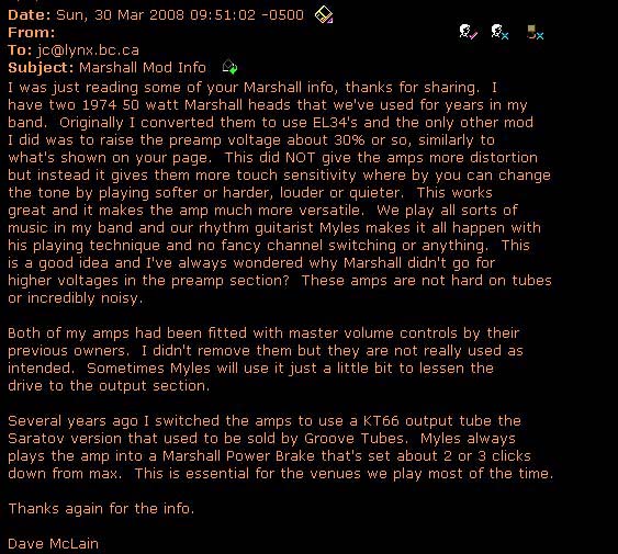

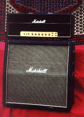
... it is relatively well known by now that the very first Marshall amps were derived directly from Fender '59 Bassman amps (JTM45), at first as dead knockoffs and later modified to produce the more raunchy and aggressive response (a higher TSR, more filtering in the Preamp and an altered output stage) ... Marshall experimented around the circuit well into the 90's either in slight variance form or in strongly hybridized form (traces of the early 5F6-A influence can even be found in the dominantly IC-based Dual Reverb JCM900 preamp circuits) ... meanwhile the power supply and output stage configurations have remained more or less stock in shape and rating (OTs always vary a bit more maybe) ... this means the focus is really on the preamp circuits since the rest of the hardware can always be relied upon to a high degree as is ...
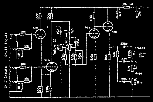
I like to discuss Marshall circuits from the 1970 schematics on, just for the ease of dealing with a more uniform design base (Plexis varied somewhat) ... there's no such thing as "a" Plexi amp just like you can't talk about just one Tweed ... also, Metalface Marshall amps ('69-'75) are sometimes regarded as the best sounding Marshalls ever made - depends on who you talk to I guess ... when I refer to the "classic" Marshall circuit I personaly like to refer to the commonly held 1970 schematic(s) ... some will surely not want to agree with this appellation, but I ignore Plexis here only to maintain a certain ease of reference ... I certainly don't ignore them as a player (!) ... personally I tend to recommend against installing any type of MV circuit in early Marshalls, because drawbacks such as fidelity loss (via introduction of extra signal caps in the signal path) and slight overall gain reduction (roughly 1/12 loading factor of 1Meg in circuit) that invariably accompanies the circuit ...
The Model 1959 Super Lead100 Marshall amp is an undeniably nice sounding circuit and many have recorded with this amp, one of the things that sets this 5F6-A derived circuit is the decoupled front end mixer almost yielding the highest level of Transient Fidelity in a guitar amp (the next level being a purely single channel signal path) ... relative to other Marshall circuits of that era there's a 0.68uF cap in the signal path that introduces more gain and dirstortion in that part of the amp ... many players sware by these Metalface amps, both in their 50w and 100w versions ...
the mods that were typically performed on Plexi and Metalface amps are usually : (i) installation of a Master Volume circuit
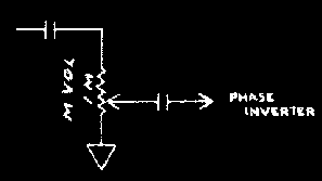
... and (ii) a cascading (not bridging) of the front end mixer circuits - this is often known as "the one-wire mod" ...
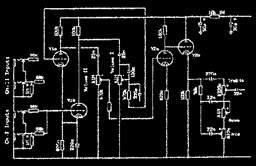
... The Master-Volume circuit (shown above) that many techs employed in the early 70's is the same as Fender's MV circuit: a typical AC-coupled1Meg voltage divider pot leading to the phase driver circuit ... the idea is that you can crank the preamp to get raspy distortion while feeding an attenuated preamp output signal to the power amp section ... unless the preamp is modded for much higher than stock levels the resulting effect is somewhat dissapointing on its own as some know ... usually this circuit requires use of a good distortion or fuzz circuit to yield potent distortion levels, certainly that's ok too depending on what's available ... the one-wire mod is the first attempt to get the distortion to high enough levels to play Black Sabbath convincingly ... the drawback to modding your Marshall with one wire is that you lose the stock sound and the distortion control has very limited spans of adjustability (especially if the MV isn't introduced) ... still in some amps I've heard (a '66 JTM45 Plexi) the one wire mod produced one amazingly raw distortion sound that certainly couldn't be laughed at ...
Following market trends Marshall later came out with its own Master Volume (2150) and Reverb (4140) amps but they don't cut it in terms of fidelity and gain like the earlier Metalface amps do ... it is pretty much agreed that the Fender 5F6-A topology has a "sound" and it so happens that any variation from it's original form (which invaribly appear when introducing a Reverb circuit especially) must be carefully weighed by risk of loosing the subtle nuances of a stock signal path ... up until 1975 almost all Marshalls maintain the "Classic Marshall" version of the 5F6-A circuit ... after that new models pop-up showing that Marshall is on the search for innovation ...
The first JCM800 Marshalls came out at a time when metal music was raging ... these Marshall offered a "brightened up" signal path, being copies of the earlier Metalface circuits but with the addition of a 470pF brightening cap in the preamp mixing circuit ... ... the early versions of JCM800s are massively well built Marshalls, featuring a large output tranny, the same standard Marshall power supply circuit and in one case a preamp circuit that mimmics earlier Metalface amplifiers (50w JCM800-1957, 100w JCM800-1959) and in the other case a cascaded distortion preamp based on the classic circuit topology known as the JCM800 "Master Volume" series (models 2103,2203,2104,2204) ... in all these amps the signal path is all-tube ...
The term "Boogie'd Amp" used to, and still does, refer to a tube amp that's had an extra gain stage "inserted" somewhere in the gain-chain of a more or less stock topology ... this doesn't necessarily mean that an extra triode vacuum tube is added to the existing hardware - it could come as a rearrangement of the existing hardware ... the art of modding tube amps for natural tube distortion came in the late 60's at a time when distortion intensity was acquiring legitimicy as a tonal requirement in the rock arsenal ... Whereas Mesa Boogie's Randall Smith's early efforts were to "Boogie" a Fender Blackface signal path (a circuit that inherently cuts back on overdriving), the idea of Boogie'ing a circuit that already has greatly distortive tendencies is what modding Marshalls is about - thus producing high levels of compressive distortion ...
Many techs agree that Marshall's attempt a creating all-tube distortion in the MV-800s is a little too polite and there was no switching arrangement so the amp could only be used in one mode - for some this might be a drawback ... rememeber that techs had been performing high-quality Boogied Marshalls well over a decade by the time Marshall came out with its own version ... the circuit I use to modify MV-800s (mainly) can be; as you can see it's based directly on the JCM800 and so a minimal amount of rewiring is incured in those amps ...
The circuits found below details a high-gain 2-channel Marshall distortion circuit ... it is a slightly more sophisticated version of the original "one wire" mod ... the goals of this circuit are twofold: (i) to produce a stock or standard type of Marshall response in the normal channel (only guaranteed by using the exact same circuit minus the two channels on the input for maximum transient fidelity) and (ii) to produce an oustanding distortion circuit capable of extreme range but more importantly capable of delivering "undeniably" beautiful overdrive and compression waveshapping effects ... not too personal or weird but nontheless lively, convincing and penetrating ... where y'still hear wood in the mix ...
...comments ...
tonally, this circuit is a generic sounding Marshall circuit in the sense that no major filtering changes have taken place from the original circuit, ie no bypass cap changes, no un-natural clipping limit changes or extra crunch factors are added (but could be) ... the gain of the boogie stage is upped quite a bit from MV JCM800 levels and the fixed halving circuit found in the MV JCM800 is now replaced by a pot which allows for extreme amounts of gain and distortion ... so much so that you can't put both volumes at 10 and not have the amp work well - things just get oversaturated then ... it would be easy and professional to adjust things so this wouldn't happen but I leave it in to show the owner how much gain there really is available ...
... the implementation of the preamp shown below switches in a "boogie" stage following a sligthly modded JCM800 Marshall front-end circuit ... the 220k grid block resistor follows the switch and so has presence in the normal channel signal path ... to save on switches and chassis drilling the two volume controls are "dependent" which means that how you set your volume for the A/normal channel will determine how you set your B volume to get high-channel characteristics; this may seem like a drawback but the values in the circuit reflect this and have been chosen so that the two are entirely compatible ...
totally independent B channel volumes can be incorporated by using extra switches but I find this to be redundant in practice ... aside from this the circuit is a stock Marshall preamp circuit and the tone control circuit is fairly wee balanced for both channels though some highs can be shunted in the boost stage by capacitatively bypassing the plate resistor there with small valued ceramic caps ... notice how the unused triode gain stage is grid grounded in the switch [preamp ckt] for when the amp is running in normal channel mode ... low end crunch can be brought in by bypassing the front end cathode circuit with a large electrolytic cap if any body wants it ... standard tricks ...
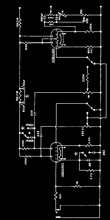
... the output stage is nearly stock aside from the dualized version of Ken Fischer's excellent Master Volume circuit adapted to a "click-free" switching circuit ... a trialized version can be incorporated to provide two masters on channel B (B1 and B2) as seen in intro picture ... the bennefit of ken's idea is that (i) it occurs in the furthest possible point in the amp -therefore not interfering with waveshaping effects previously in the amp (this means the attenuated signal approximates more what the amp would sound like if it were cranked without a master), (ii) it doesn't interfere with the biasing of the output tubes., (iii) when the master is on ten the amp is "stock" !, (iV) this circuit can be extend to accomodate multiple masters for more ellaborate arrangements (like, you could have two MV levels for your lead channel at the hit of a footswitch) ...
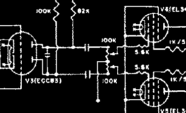
... note the difference between these two circuits in the Master Volume circuit ...
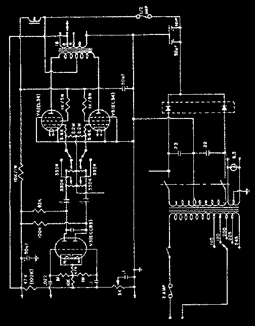
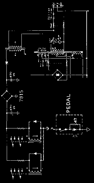
the switching circuit that makes this all work is based on a road tested supply circuit that is robust, quiet, minimal part and therefore maximized in reliability (I once made the mistake of trying to feed these coils off the zenerized 15+ volt source in a JCM900 and found that it didn't hold) ... I use a 15volt regulator with 12v relay coils ... this leaves room for an LED and some resistance to trim current levels so they match nominal closed position coil current levels, or yu could vary resistance until voltage across coil was exactly 12v in closed position including LED ...
Marshall's quest to innovate essentially lead them to leave time proven tube territory for various forms of distortion inducing circuitry - one idea being the introduction of diodes in modified versions of the classic circuits in order to produce "more intense (?)" clipping effects ... these ideas are remeniscent of fuzz pedal designs ... the distortion that these types of preamps produce tend to lack the dynamics of good overdrive circuits - the dynamics of the late-JCM800 and JCM900 amps are quite static, a fuzz that follows the same regardless of playing fynamics and is deemed "thin" by a host of people who talk about them (Deja News) ...
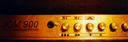
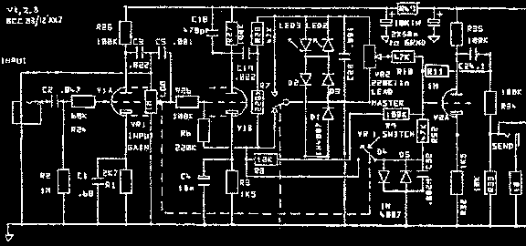
... I found that JCM900 OTs, however small, will produce a nice gnarly sound along with this 2-channel circuit though the amount of work required to do the conversion is quite considerable compared to doing it in a JCM800 ... I'd rather recommend getting an affordable and very reliable 50w JCM800 and do the mod with a single 4xspdt relay switch ...
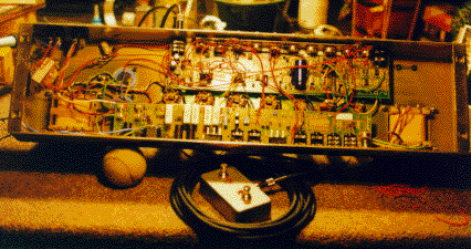
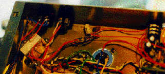
This photo shows the bridged guts of a Dual Reverb JCM900 amplifier that's been modified with the 2-channel circuit ... In true point-to-point fashion I've literaly bridged sections of the hybrid amp in order to reproduce the all-tube Mod circuits shown on this page ... to elliminate noise and instability problems the same "system" power and ground system is retained to avoid introducing ground loops and since only one triode tube section needs rewiring in "either" version of the JCM900 circuits all main rewiring of this circuit is done on only one of tube sockets ... the one version is the non-reverb 2500 series and the other being the reverb 4100 series ... For the 2550 the second 12ax7 is rewired on its socket and the Effect Loop is disabled - For the 4100 the first 12ax7 is rewired on its socket and ALL the sillicon is easily bypassed on the fly (notice how the second and third gain stage just happens to be lying nearly stock amidst all them op-amps, and the tone stack needs no modding in either amp !!
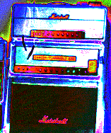
... my '73 "1959" SL100 is stock except for a lowered TSR and a snipped 0.68uF ... for some reason there's something nice about a Marshall that has a cleaner preamp, you get to taste the power tubes a little more it seems - and the sound is more together ... by paralleling 15k and 33k resistors in the right place (see diagram below) the appropiate supply nodes can be brought up in potential providing the gain stages with extended dynamic ranges and therefore lesser clipping distortion in the preamp overall ... I like these amps more or less stock, by powering the TSR we're going back towards (5F6-A) Tweed territory a little ... compare this with the TSR of my '65 Twin on the Fender page ... depending on the B+ one must be careful not to raise the voltage too high to the front of the preamp or the tubes will run too hot there too - measuring voltages following each step is a good idea ...
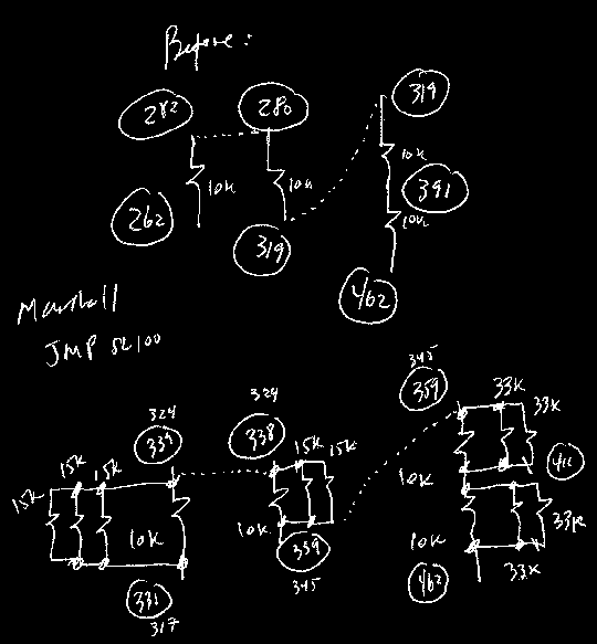
... the original filter network of the SL100 contains four 10k-Ohm 2watt resistors in series - by soldering higher valued resistors in parallel to the existing components (making sure not to overheat them) avoids any destructive operations ... no parts are snipped in this mod !
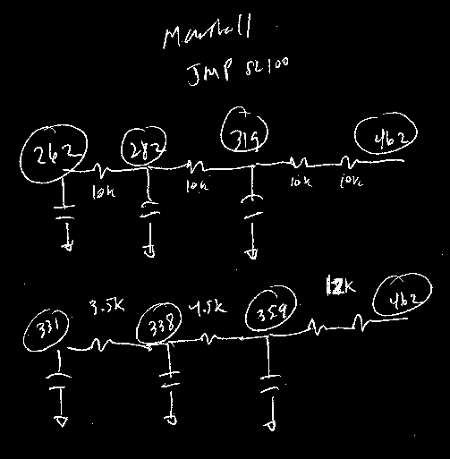
... the before and after voltage chart along with equivalent resistance values that were settled upon while tweaking the amp ... of course resistors are soldered and then measured while the amp is totally disconnected from wall power and thoroughly bled !
... my '86 JCM800 MV100 used to belong to Voivod's Bass Player, brought it over to Rick Onlsow in Montreal (also an xcellent player); ex Frank Marino tech ... Rick's circuit has four volume controls and three masters - comes with a dual-LED footswitch ... my 2-channel is somewhat based on the front end of his circuit and incorporates noise-ellimination practices I learnt from him ... these are crucial in high-gain mods or else there's no point ... his normal channel is very strong and clean, his first level distortion is extremely nice, and his high gain can range from a warmed up version of the first level distortion to a heavily saturated metal distortion and everything in between - so does my 2-level circuit except that one can't compare +1 triode distortion sound against a +2 triode distortion sound ... regretably I haven't plugged into this monster in a while ...
