From a spectral point of view two interesting things are going on in the 360
circuit. On the one side, there's the Variamp circuit; a single class-A stage providing a 5-band selectable filter function. Unlike multi-band eq circuits the relatively restricted 360 circuit exhibits
considerably less phase distortion. From a dynamic point of view all the
gain stages are devoid of capacitive bypassing in the emitter circuits.
Together they account for the type of transient response the 360 is known
for.
 |
 |
The lower graph shows the five frequency bands of the VARIAMP filter,
they are centered around: 50Hz, 100Hz, 200Hz, 400Hz and 800Hz. The EFFECT
control sets the amount of cut or boost produced by the stage. When the EFFECT
control is turned full clockwise the circuit produces maximum boost, when full
counter-clockwise the circuit produces maximum cut. When the EFFECT control is set at 12 o'clock the circuit response is flat. It's
also worth noticing how the bands become relatively narrower as they go higher in frequency - thus affecting a lesser frequency span.
In combination with the VARIAMP 5-position filter we find the passive RCA tone stack (load) typically seen in valve type circuits from the late 50's, notably in guitar and bass amplifiers. It's worth noting that the sudden BASS control jump characteristic of the RCA circuit still applies in the 360. Since the RCA tone circuit naturally produces a mid-scoop, this combined with the VARIAMP filter response yields interesting tone shaping combinations.
|
 |
The five VARIAMP frequencies are depicted as RED dots at the bottom of the tone circuit response graph to show the relative placement of frequencies between the two filter circuits. Notice how the five VARIAMP frequencies all lie somewhat within the mid-scoop area of the BASS/TREBLE tone stack filter response. It's also worth noticing that the two upper-most Variamp frequencies (at 400Hz and 800Hz) get swamped by the treble shelf when the TREBLE control is set high enough. This means that getting more use of those two upper VARIAMP positions may require turning the TREBLE control down. You can tell in the VIDEO clip (below) these two positions aren't doing too much at one point because I've got the TREBLE control set too high. The other thing to note is that the FUZZ circuit comes before all that eq'ing circuitry, so the eq. sections have a dramatic effect on the resulting FUZZ sound
as well.
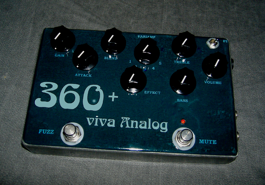
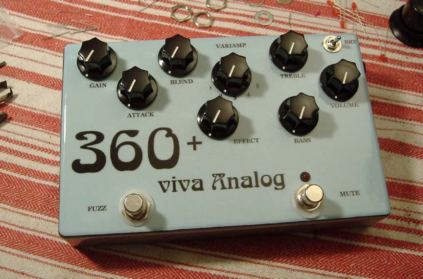
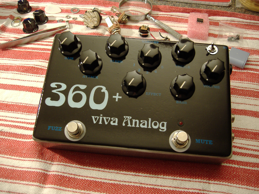
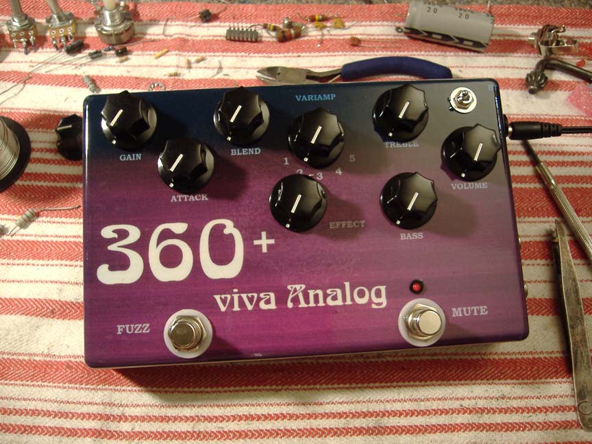
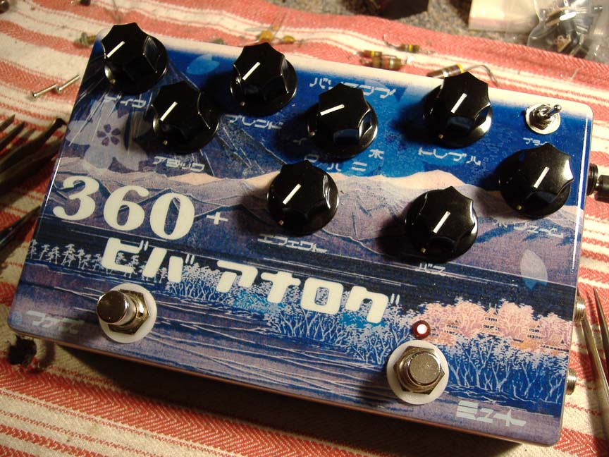
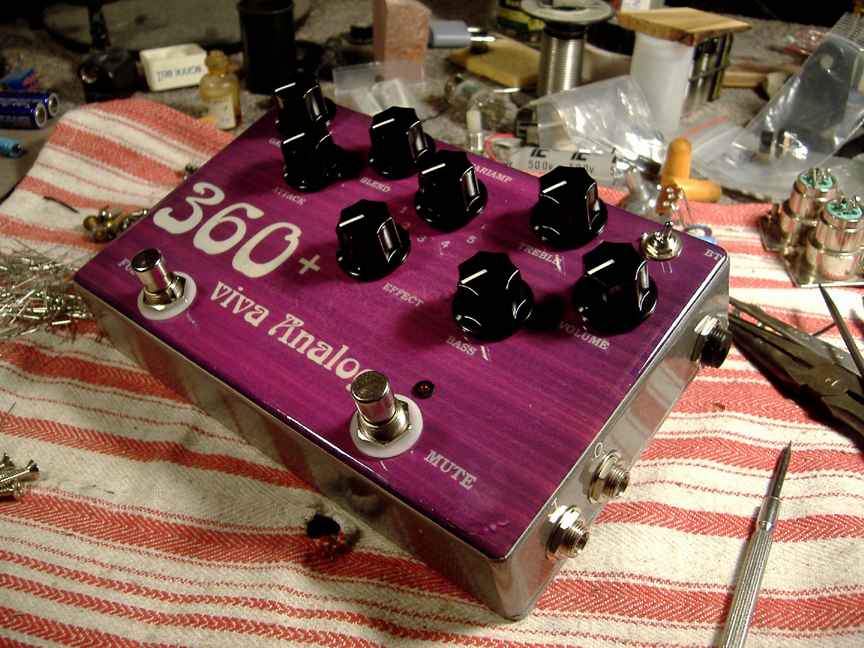
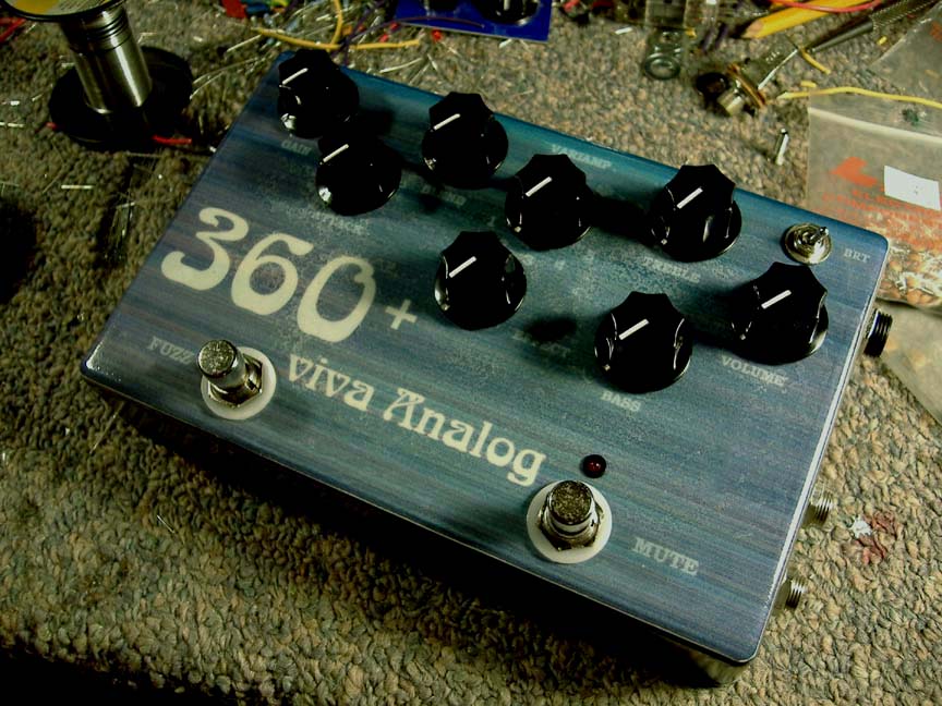
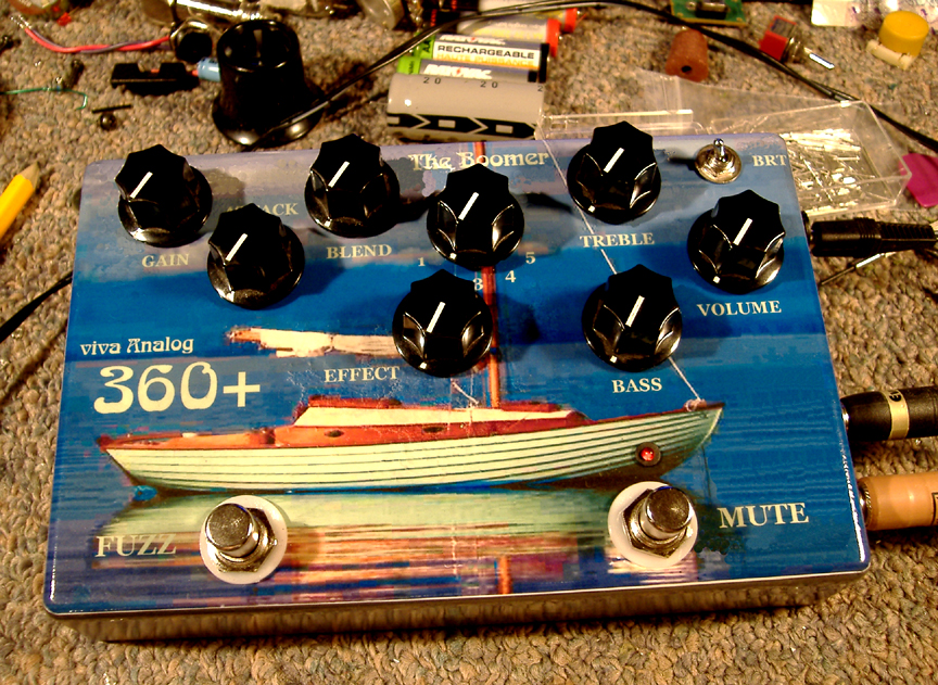
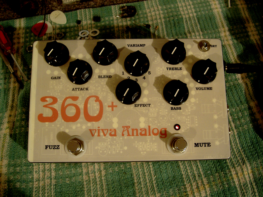
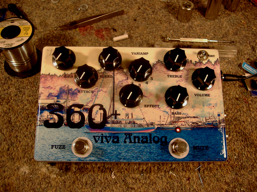
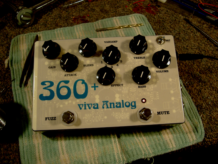
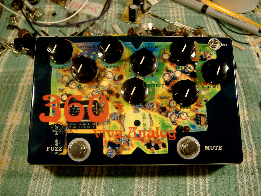
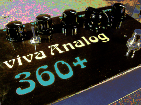
Custom "360+ Pro" Gallery
|
\\\ 360+ FUZZ DEMO ///
\\\ 2009 viva Analog 360+ DIY Bass Preamp Kit ///
 |
\\\ ARCHIVE MATERIAL ///
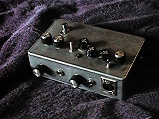
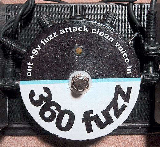
** Acoustic Control 360 Bass Preamp and Fuzz Unit (1997) **
This electric bass Fuzz/Preamp system was favoured by the likes of John-Paul Jones, Jaco Pastorius, and Larry Graham ... aside from the great sounding Germanium/Silicon combo fuzz the Acoustic 360 circuit is based around a versatile and punchy sounding class-A preamp circuit ...
 |
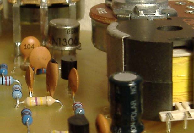
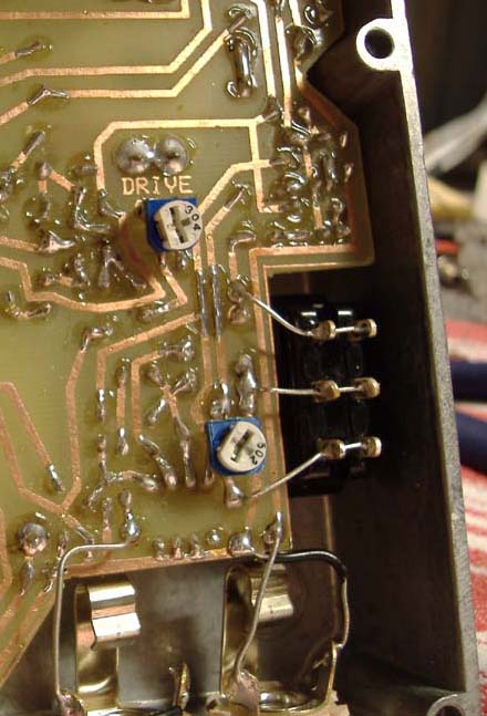
These are pics of my first 360 clone project - I used a hi-Q 1.2Hy Pultek filter coil for the Variamp section, it has both battery and DC regulated operation from an AC wall-wart ... the circuit is stock ... the original 360 had an internal ETF tuning circuit, it isn't included in any of my units (or kit) ...
 |
Acoustic 360 and 270 owned by Atsushi Sugenoya - Patron of the first "360 Earthquaker" Clone
 |
Original Mods and Building Ideas (2002)
 |
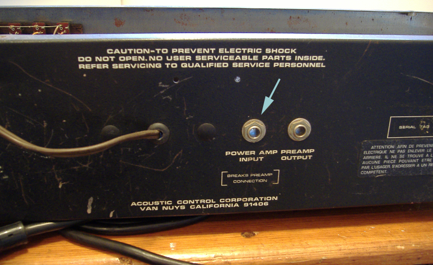
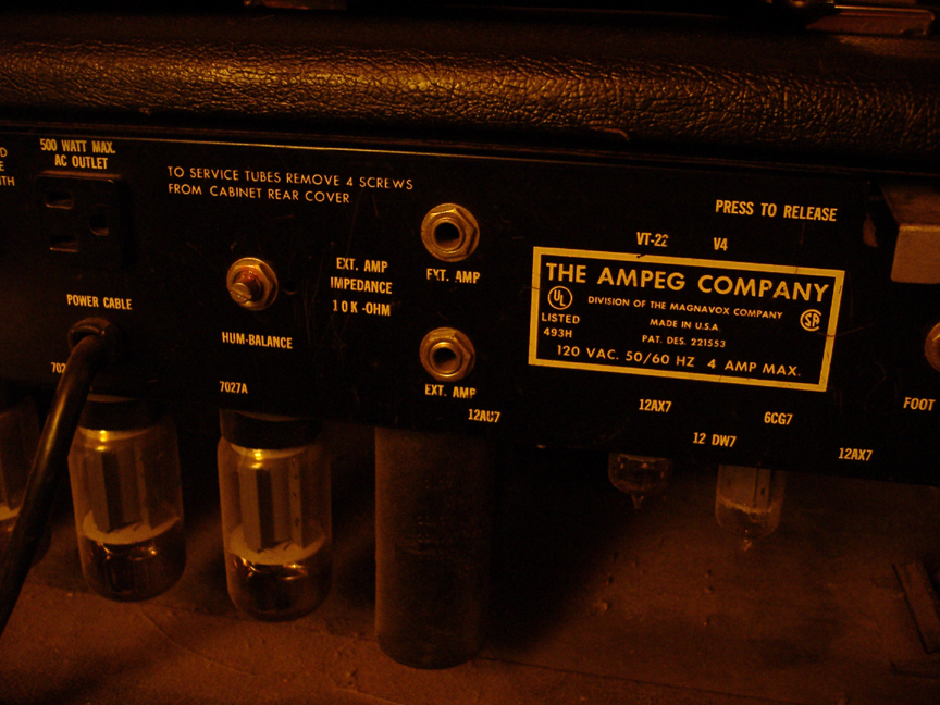
The "modernized" version of my first 360 clone includes an op-amp based output amplifier add-on to the basic circuit - this is where op-amps can provide improved system performance ... having greater output drive allows for better retaining of transient (dynamic) fidelity over the stock emitter follower ... this also allows the driving of a wider range of power amp (loads) and cable capacity (length of run) : all the way from modern stuff to old low-Z transistor power amps and low sensitivity vacuum tube slave amps ...
 |
Op-amp based DI outputs (1/4" and XLR)
 |
18v @ 26mA // Battery Version
 |
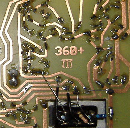
Charlie Barth's 360+ Wiring/Components-PCB Diagram
Charlie was very kind to draw a computerized layout and wiring diagram with the component placement on my
PCB board
 |
 |
Photo (c) C. Barth 2003
For those of you who are interested in the 360 Fuzz sound but not the whole preamp Charlie tells me he's come up with a gratifying circuit that does just that. Check it out !!
 |
\\\ Early Units ///
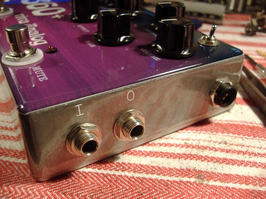
Lite/fuzz-less 360+ Pedals and full featured Racks
 |
 |
 |
 |
 |
 |
Player Comments
Hello JC,
I have been working on building an entire Acoustic 360/361 copy from scratch. I am building the entire thing making it as close electrically and physically to the original as possible.
One of the things that kind of blew my mind was the use of the 2N2926 NPN transistors as what appears to be 8V DC Zener diodes by reversing the collector and emitter (and leaving he base floating). I wonder why they did not use an actual zener diode unless the reverse 2N2926 has some special property that was needed in the design? Maybe they had a ton of 2N2926 transistors on hand at the time?
I tried using the backwards 2N2926 in the Fuzz circuit and it actually oscillated somewhat which modulated my fuzz signal. I took the 2N2926 out and put in a 7.5 zener and everything is fine now (I think).
I was just wondering what the real deal is with with these transistors (there are also two in the electronic tuner which I know is not included in your hand draw schematic (Acoustic 360+ Mods).
I also tried using a real inductor in the Variamp but I was not happy with the results so I am going to try your inductor simulator circuit instead.
One other question: As best as I can remember, the Acoustic 360 pre-amp did not have a Master Volume control (as shown on your schematic and all other 360 schematics) so I am assuming that this must have been a factory pre-set internal trim-pot (I have not had access to the real deal Acoustic 360 otherwise I would not have these questions). If so, I wonder what it was set at?
Also my electronic tuner output into the pre-amp is at a very low volume with I assume is normal as there is some high attenuation resistor voltage dividers between the Unijunction output and the pre-amp input.
B.T.W. Do you have any idea how this tuner was suppose to be used? It seems like a joke!
The plots that I send you are with the coil simulator circuit from your hand drawn 360 schematic not using an inductor. I gave up on the inductor after I found that it was not really 1.5H but more like 0.8H. Even though I used two back to back 3.3uF electrolytic caps in the simulator circuitry, the center frequencies came out extremely close to the calculated frequencies so I am just going to leave everything alone and not mess with it any more so now I am concentrating on finishing the powered speaker. I also gave up on using the upside down NPN transistors for voltage regulation and I went with regular old zener diodes.
All I have to do is build the compression chamber (that what I call it anyway), mount the 18" Vega and then install it in the cabinet. I am now trying to track down some Formica that matches the acoustic blue to go on the front of the compression chamber. I will take some pictures when I am done.
Jeffrey Hicks
Associate Engineer
Audio Technica, US., Inc.
Thanks Jeff! the electronic inductor simulator works pretty well in this adaptation of the Variamp circuit, except for the slight increase in hiss at full boost or cut, it's almost as good sounding as a high quality coil - quite close in fact. About the Zener connected transistor, I had the same problem with all the modern devices I tried, maybe the hFE has to be low or something - ended up using a Zener as well. Interestingly, the three VCOs in the EMS Synthi and VCS3 synths are all based around a transistor connected the same way - and obviously designed to oscillate.
I'm heading to Montreal to do the Guitar Show in July, if you are around for the Jazz Festival come see me. I'm bringing an Archtop Bass with me.
Thanks again for a great device-It's all I use to record with, my amp went on vacation after the first time I used my 360+
Vinny
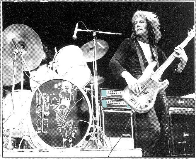 |
Greg Ridley of Humble Pie - yeah!
EMAIL: jc AT lynx DOT net
| |