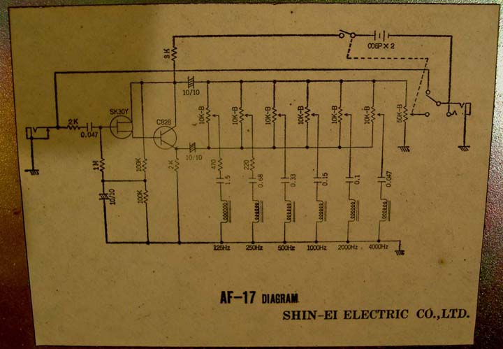
ShinEi - AF17 Graphic Eq Emulator
Photos and Text (c) JC Maillet 2006
 |
Possibly made by Garnet in Winnipeg during the 60's under contract for Shin-Ei - interesting ...
 |
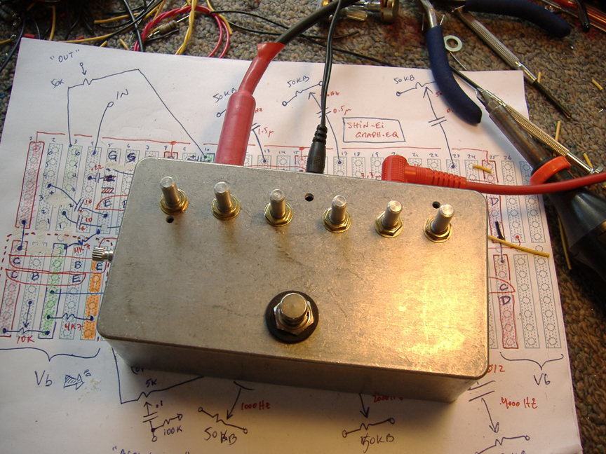
A number of people have asked me for the details of this curious build and so here they are. The inductor emulators are single-ended "active inductors" circuits, not exactly Gyrators - I got the idea of using a jFET buffered Darlington from the front end of the stock circuit (where else ?!) I had to mod the front end to get it to work with my devices ... the circuit pulls a fair bit of current as is I'm assuming the power supply will be wall-wart and also, as a result, I don't have to use adaptive biasing in the front to account for a dying battery ...
Note: the emitter resistors on the active inductor circuit sets bias current, this is where lots of the current is flowing ... these resistors could be made larger for less bias current, I'd try 10k or even 100k just to see if it still works ... if you find a emitter resistor value that is high enough and still works let me know what value you come up with and what the total supply current becomes ... I would also probably increase the Drain resistor to 5k6 or 6k8 for slightly over-unity average gain as in the original ...
All active inductors are given 1k of internal resistance, which was sheepish on my part ... you might want to try dual 220 ohms or dual 100 for a more realistic value - in fact these valuee should decrease comensurably as the inductors decrease in values for increasing frequencies ... the idea would be to scale resistance by corresponding inductance ... yeah, there's lot to experiment with here - so go for it and check it all out ...
Of course, at full boost/cut these types of filters filters are a little noisier than their "physical" inductor counterpart but still this circuit does the job as a cool sounding booster ... lemme know what you think ...
EMAIL: jc AT lynx DOT net