What's with all this Transfer Curvature stuff Anyway ??
JC Maillet (c) 2009
Traditional Triode Biasing
Electronic signal amplification came along once the thermionic "Triode" tube came into being and a circuit such as the one shown below was devised. In its simplest form, an input (ground referenced) voltage source is directly applied to the Grid terminal of the Triode to produce an "output" voltage variation at the Plate terminal - hopefully many times larger than the input. This is a common way to understanding Common-Cathode Triode gain stage action, but in fact there's an intermediate step that needs to be considered carefully.
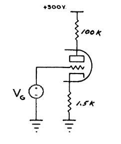 |
Without realising it, DeForest's circuit came to produce non-idealities which still mystifies audio minded folks over a hundred years later. Since the birth of electronics and the first examples of the Thermionic devices many different types of devices and circuit design styles have emerged, and to this day it is difficult to say if anything else can "act" the way certain arrangments of Vacuum Tube circuitry do - and if they did certainly a complete explanation is still missing. Since there seems to be some interest in knowing whether we can duplicate Tube circuit behavior using other types of devices and circuit configurations it would seem to be a good idea to first outline what "it" is about Tube circuits that we're attempting to emulate.
In the early stages of my research I started wondering about the DC Transfer and TRANsient response nature of cascaded tube circuits when I noticed that pretty much everybody who looked at tube circuit performance did so mostly using harmonic distortion analysis - a very limited yard-stick as I see it, at best a trivializing "shadow figure" when seen from a mathematical mapping standpoint. With the advent of Spice for personal computers it became possible to end the speculations and perform serious research at home. In my case I did all my modeling and simulation work on the very first 68040 FPU Macintosh machines, a '94 Quadra 640, and student copies of both Matlab and Pspice 5.0. These two high powered softwares was all I needed to devise high-accuracy models of the 12ax7 and 12at7 triodes and carry through with characterization simulations of gain stages and even entire preamp circuits if I wanted. The ground-work was completed in 1996, I published an article on my modeling technique in Glass Audio 2/98 and my Tube amplifier book IF&MTA was published in 2001. The curves shown here, taken from IF&MTA reveal the kind of results that motiviated me to spend 10 months cranking out the numbers by hand.
 |
The main thing about the top set of graphs is that it shows how the standard gain stage shifts its Transfer specs as we vary the Cathode resistance against a constant supply voltage and Plate load resistance. This is the sort of thing a person interested in tweaking tube amplifier circuit might want to see - the first part of IF&MTA consists of dispalying of such technical artifacts related to the main Triode gain stage configurations (Common Cathode, Common-Plate, long-tail Pairs). These curves along with the accompanying first-derivative curves shown on the bottom part reveal a nearly full picture of why Triode gain stages do what they do in terms of Harmonic Distortion production (note: the case where a bypass capacitor is included in the Cathode circuit requires extra work and is more complex in behavior still). This comes from the curvature of the Transfer response - any student of Fourier Analysis would be able to see how this is so when looking the horizontal axis as the signal input - presumably around the zero volt origin, being ground referenced in most cases - and in this case the output corresponds to what the curve points to for output (a different one for each Cathode resistance value chosen in the 0 ohm to 2k5 ohm range). Provided there is no reactive element elsewhere in the circuit, such as a capacitive bypass on the Cathode resistance for example, and the Grid circuit current is producing negligeable amounts of its own brand of non-linear effects (that's another topic of discussion), then the input/output relationship will be perfectly described directly by these Transfer curves - thus producing a locus of input/output point pairs. The cases where reactive elements are present is not discussed here.
A few observations are plainly evident. First, on the top left side of the graph we notice that for all curves the gradual tapering of the response curves is the same - this is the "soft-cutoff" engineers refer to - notice how this applies to all curves regardless of Cathode resistance value. The next thing to notice is how "stretched-out" the curves get relative to input signal range (x-axis around 0v) as Cathode resistance increases in value - this is the effect of local (negative) feedback within the gain stage itself. To understand this we need to consider an intermediate step in the production of output voltage, and this is the intermediate current which is flowing through the Triode. Another thing to notice is the existence of a saturation input level in which the output stops dropping past a certain point. The Saturation point and the soft cutoff region could determine, for example, the clipping limits that occur when using such a gain stage as a distortin stage.
One of the original aspects of my work was to present first-derivative plots of the Transfer curves as a means of establishing other conclusions regarding Harmonic distortion specs and the like (see "Inside Fender and Marshall Tube Amps" ISBN 0-9684849-0-5). In a nutshell, the derivative graph shows where the inflection points of the direct Transfer curves lie. The logic is mere heuristics and it goes like this: the area where the derivative is nearly constant (at the bottom) is an area where the original Transfer curve is "most" linear in virtue of the fact that the derivative of a linear function is a constant - and in th case of such matical-physics curves the reversed can be loosely infered. The interesting thing about this is the fact that the inflection point moves to the right as Rc increases - and in fact suggests that the best resistance value lies between 0 ohm and 500 ohm if aiming the best Harmonic Distortion figure at the the 0 input crossing point. This is an example of why it not only necessary for a Spice device model to be accurate in absolute value but also in the first derivative. The curve corresponding to 0 ohm for example, would correspond to the Transfer one gets when Grid-biasing a triode as in the inoput stages of a Fender 5E3 Deluxe for example - being the most curved it would produce, in itself, the most harmonics per amount of input signal compared to an input gain stage biased by a resistor appreciably greater than 0 ohm in value.
Traditional jFET Biasing
On the drawing shown above we start by comparing the DC Transfer of an n-channel jFET device with and without the usual primary source of localized Negative Feedback. The main thing to note is the "loss" of Transfer curvature as the amount of resistance is increased in the Source circuit. Traditionally, when we operate with a grounded Grid some degree of resistance is necessitated in the Source circuit otherwise it is impossible to obtain any headroom range since the the Gate turn-on "abyss" (where Vgs turns positive) lies right on the Y-axis.
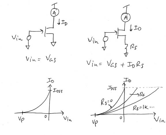 |
As we increase the Source circuit resistance the point where Id=Idss is reached (ie., @Vgs=0) moves to the right and the curve starts getting stretched out (note: this profile drawing holds provided Rs is not chosen too large so that Idss*Rs is less than Vsupply). As the resistance increases further the Transfer curve becomes more linear relative to signal amplitudes as a result. Thus, the common approach to biasing jFET gain stage yields a linearization as a byproduct of attempting to stick the Quiescent operating point (Vg=0) somewhere inside the Current operating range of the device through the inclusion of resistance.
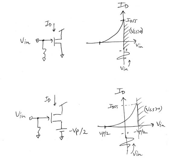 |
If we are seeking to replicate the intrinsic curvature of a Triode circuit by way of using the similar Transfer curvature characteristic of a jFET device then introducing resistance in the Source circuit as an exclussive means is not the way to go. In other words, we seek a way to move the operating point inside the curved area without loosing the curvature - this means producing a DC shift while introducing no appreciable amount of resistive NFB in the Source circuit.
There are several ways of doing this - the method shown below simply consists of applying a DC voltage to the Source via an op-amp. In effect, this shifts the Transfer curve over the Quiescent operating point (@Vg=0) thus achieving our two-fold goal. There are several other ways of doin this that I know of but the practicality of this approach also allows continuous variation (tuning) of the relative position of the Quiescent Bias point inside the curve and at the same time setting the idling current level. This does a few things for us : (i) by being able to set the bias point we can control the AC gain at the Quiescent point and (ii) also the standby Noise level, (iii) we can set the signal limits for desired output shape and headroom, and (iv) the exact value of Vp isn't required to be known in advance - only a rough estimate suffices.
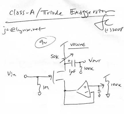
By using an op-amp as a near-ideal voltage source and then converting the jFET Drain/Source Current to a voltage through a Drain load resistor we can produce an output voltage that mimmicks the shape of the non-linear jFET Transfer current since a scalar product (r*I=V) is linear by definition. By making the resistor variable we obtain a simple volume control and thus implement a variable output non-linear booster circuit. When Triode circuits operate without localized negative feedback in the Cathode circuit they roughly produce a 3/2 (1.5) power Transfer function; and when jFET circuits operate without localized negative feedback in the Source circuit they roughly produce a 2nd power Transfer function. We can then regard this non-degenerated/shifted jFET circuit as producing a greater output of similarly induced harmonics than its Triodic counterpart by way of a greater order of curvature - more importantly this curvature profile similarity extends to both extreme limits of operation (cutoff and saturation). Hence this circuit can be seen to produce an exaggerated Triode action in terms of dynamic harmonic production. Other important ramifications exist as well ...
For example, driving this circuit into a Common-Cathode Triode or Common-Source/MU-stage n-channel jFET gain stage can produce an exaggerated compression effect provided the output of the Booster circuit dips low enough on the "negative" side of the waveform relative to the dynamic input range of the following gain stage - this result is musical and remeniscent of Cathode biased tube output stages.
EMAIL: jc AT lynx DOT net