It's not that guitar amps weren't around at the same time or before but to many players Fender amps are the center of the galaxy when it comes to a first great experience in guitar amplifiers ... the reasons have been well documented, Leo even said it himself that Fender amps took off once he found the right speaker (Jensens) ... quite a humble guy considering some of the great innovations that went on inside his amp chassis over a couple decades ...
... 1958 is the year that saw the Tweed Bassman 5F6-A and Tweed Twin 5F8-A; they really shook the music world - so much that the second most famous tube amp in the world (Marshall) based their whole line of amp designs spanning several decades as well on that very '58-'59 Fender circuit, and only IT really ... Traynor as well also paid homage to the famous circuit in their early BassMaster YBA-1 and BassMaster MkII YBA-1A ...
Because original Tweed Twins and Bassmans are difficult to encounter most of us experience the Tweed circuit in moddified form through either Marshalls or Traynors ... the distinct response of the circuit can be heard despite changes in hardware configurations ... it is not surprise that most hobbiests choose this circuit as their first "franky" ... and it is very popular as a mod circuit provided there are three triode tubes available ... the Tweed 5F6-A and 5F8-A topology (meaning the "connectivity map" of all components tied together) is a good place for a novice and expert to start studying tube amp circuits again and again; mainly because many of the circuit forms that first appeared in this circuit were subsequently maintained by Fender (mainly the phase driver, output stage and power supply circuits) and seemingly adopted in modified form throughout the industry thereon after ... classic building blocks !!
one of the striking features about the 5F6/8-A topology is the simplicity and economy of components used in making these amps, there is a strong correlation between part number and tone clarity in audio circuits ... the first thing is to map out three regions of the amplifier: the Power Supply circuit, the Output Stage, and the Preamp circuit ... since the first two seem so standard, most of us initially focus most of our attention on the "more fun" preamp circuit (see below) ...
A complete redrawing of the original schematic with tubes replaced by their respective "current sinking" network element equivalents can be pulled from the link below ... in it one can more easily trace the major flow routes of current throughout the entire amp (important !) ... if necessary, the relative magnitude of these currents can be estimated once the number of tubes and their activity level determined ... regardless of the exact levels, the qualitative information provided by the schematic is enough to understand quite a bit about what the circuit is trying to do during idling (DC) and processing (non-linear AC) ...
A technical description of each part of the amp will eventually be provided here and in the revised edition of my tube amp manual (the current version of IFMTA doesn't really teach tube electronics, it rather assumes you've got a bit of tube DIY experience ...) ... once you understand that only the tubes "sink" current from the power supply (they're really just about the only DC path to ground in the amp aside the 220k resistor ladder present when the B+ caps are stacked) or from leaky (faulty) filter caps - this can aid in debugging tube circuits later ...
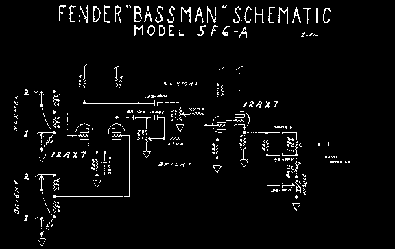
The Tweed 5F6-A and 5F8-A preamps are identical, they sport a "commonly biased" differential) front end mixer circuit, a very straight gain stage cascade (little to no interstage "grid blocking" resistance) , an odd'harmonic producing cathode follower - never seen again thereafter in the Fender library, followed by a vertically shaped frequency-selective tone "stack" impedance, a departure from the previous shunting circuits ... from there the signal goes capacitively coupled to the output stage ... the role of the preamp being to build up enough signal voltage (low power, meaning low current and therefore a high enough circuit impedance) to drive the output stage which has a triode front end (which sink little to no grid current during typical medium level signal levels) ...
Several things make this preamp unique; first of all would be the "simplicity" aspect of the circuit - it sounds as clear as it looks especially when simplified into a single channel circuit (i.e. without a mixer) or with bias decoupled (see Marshall 1989) ... the lack of interstage resistance is a source of preamp distortion that makes the circuit in part ideal for gutsy playing depending on the rest of the amp ... as well, the tone stack values are worshiped by many (I do) - I find that many tube amps bennefit from a Tweed Stack translant regardless of other stock/non-stock issues ... it seems that the Bass "hump" is not as pronounded as a Blackface tone stack and there's an overall shift in the Tweed values that seem very friendly and balanced to most guitars ...
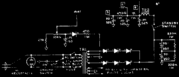
The stock '63 Bias circuit is shown here with no improvements and should be compared to the 5F6-A power supply for similarities and differences ... the type of rectification coming off the secondary high voltage windings playes a large part in setting amplifier dynamics - either diode or tube ... tube rectifiers introduce a substantial amount of B+ sagging during high transient activity in the output stage (power tubes sinking lots of current on a per-cycle average) ... diode rectification is desireable for players who like a firmer and more crisp transient power handling - early Marshall JTM45 can be regarded in some ways as diode-rectified Tweed Bassmans ...
Because electrolytic caps were costly way back (producing huge savings at the end of the year for a factory that cut costs right), today one can afford to replace the 70yF caps by 100uF bringing the resultant B+ capacity to a typical 50uF - this tightens up the low end a bit and gives the amp a slightly more solid feel without stiff'ing it ... installing overly large values is a bad idea as it can fry the power tranny slowly over time if streesed to high enough levels ... the preamp caps in general are not altered in value since the preamp is very sensitive to them and looses it's "dancing" quality if strapped down too hard ...
... if converting a tube rectified amp to diodes the B+ and all other voltages will rise accordingly - this is a problem for the Deluxe reverb (either a Zener diode or replaced power tranny is needed) but not for the Super Reverb ... in fact, diode rectified and fitted with EL34s and 5F-A circuit the Super starts sounding very much like a JTM45 ...
As mentioned in the bias conversion page, an additional order of filtration can be added directly to the bias pot "sweeper" (middle) terminal ... this brings the idling hum down by a considerable amount in some amps ... 50uF/75v is ok in most circuits (measure the max bias voltage to make sure)
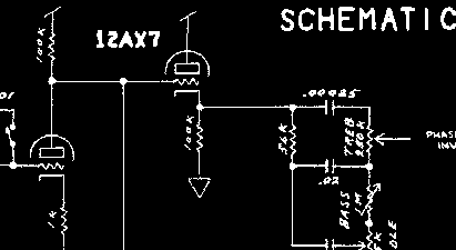
It is now time to discuss a mystery aspect of the power supply, namely the preamp power distribution network ... first the caps, if they're too small in value ghosting and motorboating effects may be induced - if they're too large the amp will sound really dead unless the network resistance level is high (as in Marshalls) ... in Fenders it is often a mistake to bring the cap values up from their 20-22uF values, some say 30-32uF is good too but generally speaking 50uF and higher filter caps are tone killers in amps that have otherwise the capacity to have the bias dance a little with the signal, a very subtle aspect of tube gear that is overlooked ... Now the resistors in the preamp filter network ... if you notice these values are almost always higher on the front side (here 4.7k) and the one up current is lower (here at 1kOhm) ... if you go through all the tube amp schematics and simply keep rack of the resistors found in this part of the circuit you'll begin to associate certain dynamic traits with the "overall resistance levels" ... One of the reasons I developed Spice was so I could study the relationship of bias dependency on gain transfer, not just the small signal value but the observation of the non-linearity ranges as a result ... I'll just show one such plot, pretty much the most important plot really ... namely small-signal transconductance against varying supply levels ...
by producing wide-range triode Spice models I gave my self the great luxury of peering into the intrinsic non-linear transfer specs as it interacts with terminal resistors to produce an "adiavoltaic" sweep ... the results were very startling ... by using a 12ax7 model in fairly typical gain stage parametric setting (values above) wide-range transfer specs can be derived for the gain stage itself in the same way device specs are swept ... granted the intrinsic transfer specs are a simplified view of the "path of states" the network variables will trace ... in reality the non-linear "anti-causal" (not following cause and effect in time - ie, having a nice little life of it's own !) probably produces a path-of-states SPACE which would consis of of a wiggly cloud hovering around the curves produced by the adiavoltaic sweep curves ... and of course these SPACES would be directly associated with outside circuitry driving and loading the gain stage - quite a complexity as seen from a mathematical descriptive ... no wounder these things hold so much curiosity, every time you play the same tube amp the "dance of bias" follows a different, however subtle, path of states ...
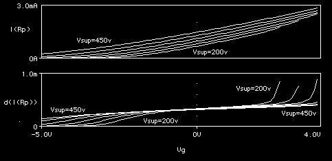
by plotting the direct transfer variable against it's first derivative function (contributing a large scale view of gain as it evolves away from the center ppoint at zero volts ... let me explain if you're not sure about graphs like this one ... imagine you've got your hand on a bipolar (+/-) DC voltage generator and you can measure tube currents and voltages as you sweep the voltage *slowly enough* (outside of internal device time limitation agents) as you measure away ... hence on this graph, the grid voltage is being swept from -5v to +4v with respect to ground - i.e., on the horizontal scale and the top curve shows the plate current lying around 0mA (vertical scale at left) the the grid lies around the negative limit while plate current lies at around 3mA for grid voltages approaching +4volt with respect to ground ... but this transfer scenario will vary with supply voltage levels as can seen there ... what we are really interest in are the small-signal parameters such as transconductance (dIp/dVg), grid resistance (dVg/dIg), and plate resistance (d(Vp-Vc)/dIp=-dVc/dIp ... all these are easily produced with Pspice's onboard math functions ... in this case I'm focusing on the gain-stage transconductance since, really it is a direct reflection of gain-stage voltage gain since dVp/dVg = gm * Rp = Rp * (dIp/dVg) ... hence the graph for dVp/dVg gain stage Vout/Vin = Vp/Vg "voltage self-gain" (i.e. unloaded externally and ideally driven) is nothing more than a verticaly scaled version of the intrinsic unloaded transconductance plots ...
you may wonder, why mess with derivatives anyway ? ... two reasons, gain stage gain levels are read directly at their zero volt crossing (idling conditions for the grid in real life lies only at most a few milli-volts away inducing little error in the simplification of choice) ... second, by plotting the derivative functions of the primary variables one can see things the direct curves don't reveal immediately ...
Several surprises pop to our eyes, although plate current levels are directly sensitive to supply voltage variations the derivative curve below shows that the zero-crossing evels still all lie pretty much at the same value ... also notice that there's a roughly "cubic" profile (a roughly linear middle part with two flanks going up and down in opposite quadrants of the plane) to all the derivative curves below - the main difference is that the inner "roughly linear" part is either extended (with higher supply voltages providing a wider band for this region ... someone who inetended to have signal levels live only the roughly linear derivative part would want to know that every added 50v of supply voltage adds roughly an extra volt of "headroom" in some sense ...
Since the derivative plot dIp/dVg(Vpc*,Vgc) is roughly linear in a middle region we can affirm that the plate transfer function itself (the anti derivative of the derivative function Ip(Vpc*,Vgc) would be roughly quadratic in that range, ie procuding dominant second harmonics as long as signal amplitudes remain in a given range provided by gain stage parameters ... over the totality of the range we see large scale roughly cubic behavior in the drivative plot and so infer similarly quadratic functional characteristics over that range - hence forsignal amplitude expending into those wider ranges we would expect a dominant fourth harmonic accompanied by strong thrid and second depnding on the exact nature of the derivative non-linearity ... an interesting study perhaps ...
By far the most important result, aside from peering into the shape qualities of our gain stage non-linear finger-print, is gaining an understanding that triode based Common Cathode circuits suffer minimal small-signal transconducrance/voltage gain losses - not as expected ... this means that preamp circuits can be transplanted from one platform to another (mainly from one supply level to another) and not experience in changes in overall gain characteristics ... this is important now for two reasons: (i) you can expect a transplanted circuit to remain stable (non oscillatory) in a new platform if it already was somewhere else ... (ii) you can expect the tonal characteristics to be maintained although the dynamic characteristics will of course vary with headroom ... so this is cool, you can increase gain stage headroom without having to worry about gain flying through the ceiling or anything ... so if you wanted to have the preamp distort less you'd increase the voltage to the supply somewhat ...
Of course, this information is not new, everybody who tinkers with tube ckts eventually gets some kind of intuitive feel for what's going on here anyway ... proof being that the 5F6-A Bassman circuit finds it's way in all kinds of platforms and it always seems to retain it's identity somehow ... in order to increase the headroom in the preamp the two resistors mentioned above in the preamp filter circuit need to be lowered ... in high headroom amps like a stock blackface Twin they are as shown above (4.7+1=5.7k Ohm) ... in a Deluxe and Vibrolux they lie at 10+10=20k Ohm ... in Marshalls they starve their front end with 40k total TSR, for a very sparkly response - the first thhing many techs explore is the exaggerating of the marshall circuit by changing the 100k plate loads by 220k loads which takes the design downhill suggesting how the original front-end JTM45 tweak to the Bassman is right on the edge ...
... in amps that get a diode rectification and have the resistors lowered can expect a dramataic increase in headroom while experiencing little other change excpet for a little brightness that comes from a bias dependent reduction in device inter-terminal parasitics which essentially determine the upper cutoff response of the gain stages and cascaded preamp circuits mde up of them as well - mainly through the dominant Miller Effect ...
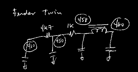
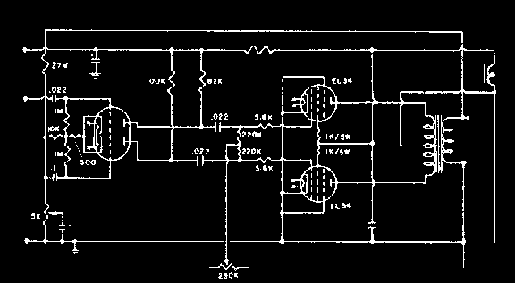
the third circuit block is really the most complexe because it consists first of a single-to-differential gain circuit which always drives a direct biased (only a few early Fenders had Cathode Self-Biasing) class-AB push-pull circuit all strapped together by a negative feedback loop ... there are several tried circuits to choose from in the Fender (and perhaps Marshall) library ... I tend to stick to three flavours of phase-driver and output circuit combinations (i) Tweed, (ii) Hot Blackface and (iii) Marshall ... the gain of the phase driver is again largely invariant to supply voltage variation and the gain levels are principaly established by the cathode to ground resistance ... in the Silverface/Blackface amps this resistance lies at around 22k, the Tweed at 15k and the Marshall same as Tweed ... I used the Marshall parameter set when converting my Super to EL34's and it has been working fine - very worth the try ...
To get a convincing SRV type "Heavy Pentode" colour from a Super Reverb it is not enough to simply convert the amp to Blackface specs, the magic ingredient derived from a Showman schematic plus the disconnection of the vibrato loader are thought to be the ticket by many blues nuts ... since there is a combination of minor tweaks that all fit together to make such a package nice and rounded I'll simply pass on the secret spice right, right now ...
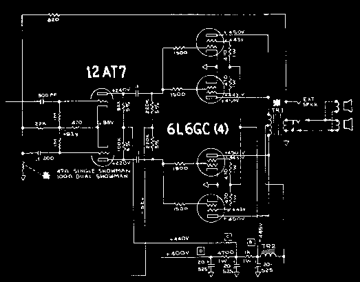
That's right, in a 6L6 Fender push-pull amp change the 100 Ohm resistor to a 47 Ohm one on the base of the phase driver circuit and disconnect the vibarto intensity pot from the preamp signal path --- you should be in SRV territory after making sure the CBS stuff had been converted to BlackFace specs ... if you lower the TSR then the pentode effect gets exaggerated a little, if you diode rectify you're getting punchy, tight and accurate dynamics, a few more uFarads in the B+ caps and yer there ... bliss level #1 ... if attempt to completely disconnect feedback circuit is made then the phase driver will produce a substantially weakened "+" plate voltage and some power and dynamics loss should be expected from the output stage due to unbalanced differential operation ... you be the judge when spankin' ...
.gif)
If you've ever played with bias modulated amps (in good working condition) such as Traynors and many early Fenders you know that this type of system makes the photocell circuit sound rather lifeless ... the advantage of considering taking the vibrato circuit off the preamp of a Modded Silverface Reverb amp and fixing it to the output circuit is that it provides us with leasure to do interesting things with the preamp, like choose another circuit ... for one it comes in handy with the Hot-Blackface conversions described just above here, for another it allows totally different preamp circuits to come in without any functional constraint worries ...
interms of "platform exportability" the vibrato oscillator and follower tube relies on minimal available transconductance levels which, being triodes, again are guaranteed by the above analysis ... so succesful export of one triode preamp "idea" to another amplifier platform is almost guaranteed (provided power supply feedthrough safeguards are in place) ... hence I know the 6G16 Vibroverb Vibrato system (maybe regarded as the finest fender vibrato circuit) will work in my '65 Twin even though I'm running on a B+ of 460 volts ...
... the only care in operating this circuit is by making sure the output signal isn't hitting the power tubes too hard at any time or they will be brought out of their normal bias range and turn red hot and eventually die (you need to watch this periodically - the price to pay for such great joy !) ... here I'll supply a few schematics that will serve the purposes of thos who want to try the magic out ...
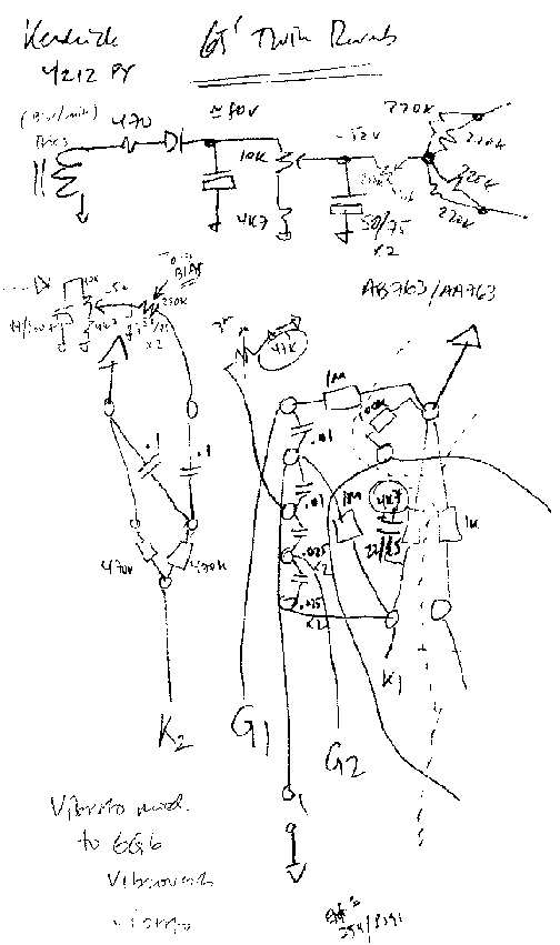
... the only remaining circuit found in a moddable Silverface amps is the Reverb circuit ... because of the unusually high drive levels a knocking effect is often heard bouncing back and forth through the springs as the intitial front wave of a signal transient causes this relatively harsh quality to the stock Blackface/Silverface Reverb system, some call it the Venture's reverb ... in '95 Gerald Weber (Kendrick Amps) wrote a great article about Finland's Sampo Kolkki's work on the 2-channel Vibrato/Reverb preamp ... he simply uses a patch chord to run from the spring can output to the inpur of the normal channel ... what this achieves is added eq to the reverb and a volume control as in the stock case.
This idea is easy to augment if it is wired inside the amp permanently ... this way we make use of the redundant Reverb control knowb and turn it into a Dwell, also I like to take the feed to reverb driver from off the plate of the first gain stage instead of the second which follows the dry channels gain level ... this way complete independence in reverb/dry channels is achieved ... know, armed with a dwell control you can reduce the drive level to the point where the springs are excited just enough without causing repetitive knocking in the can while the normal channel section affords totally independent eq. and level on the recovery allowing for a perfect mix ... with the controls set just right you can "wake" the reverb effect when stinging a note hard or having the reverb lay out a bit when struming less hard - this way the Reverb has become more dynamic and musical ...
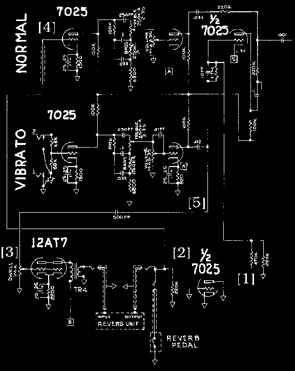
Sampo Kolkki's idea is so good that it went into a few hot blackface mods I did and it played really well in those circuits ... but I'm a Marshall/Tweed kinda guy, I like the sound of that signal path a lot, especially when given lots of headroom !! One day while hunting for mushrooms in the Haida Gwaii islands the idea came to me of using "plate-to-plate direct coupling" as a means of avoiding the typical RC mixing network which would in some way automatically interfere, at least somewhere, with the tonal blueprint of the original Tweed circuit ... at the time I thought I had discovered an unknown tube circuit technique but funny enough it's used in Hiwatt and Ampeg amps amongst others ... after many years of playing both a '65 Twin and a '69 Super housing this preamp circuit I can safely say that I have no misgivings about sharing this circuit with you ... it's gorgeous in a Traynor YGL3 mkIII also, and pretty universal by nature ...
... again, in order to combine reverb to the famous Tweed signal path without altering its "tonal and dynamic" characteristics the ideal of "direct coupling" is used between the plate of the reverb recovery amplifier and the plate of a gain stage in the Tweed preamp ... the feed to the reverb is generally regarded as a low load and both conditions offer great chances of preserving a basic Tweed Bassman imprint in this "Tweed-Reverb" Hybrid - Clone ...
note: this circuit may not be used for manufacturing purposes although I am happy for anyone to make free use of this circuit in their own projects or for friends ... in the case where you do make some cash from this work however, a small donation to a homeless person is kindly requested ...
... the accomplishment of this true AC/DC coupling scheme is key in that it avoids secondary effects and aberances that may not be part of the intended Tweed blueprint (both tonal and dynamic) ... these could come in the guise of say, a large signal dynamic range reduction (due to the pairing of "similar type" circuit nodes)or just overall loss of the classic Tweed signal path's "transient fidelity" imprint ... employing a single channel approach also assures the smallest possible amount of bias circuit-borne and mechanical ringing and so optimizing the circuit fro Transient Accuracy and Fidelity, independently of overdrive conditions ... since the only thing that changes the original circuit, it can be well argued, is the equivalent AC load at that point in the circuit - by at most a factor of two - this can be compensated by somewhere else in the overall gain product if need be to taste anyway ... in fact, since this is only a single channel design the mixing circuit found in the early stages of the 5F6/8-A circuit - which accomplishes a gain reduction of two in the product of gains - is ellimenated to maintain the overall AC gain of the preamp ... of course two 470k resistors could be inserted to mimmic tghe original Tweed circuit (with one channel's volume pot turned to 0 ) ...
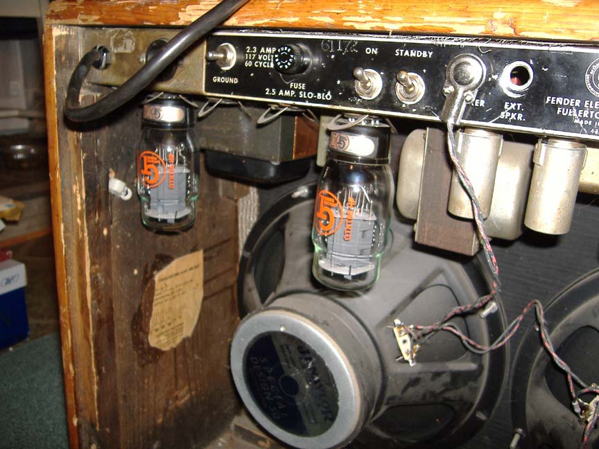
This '65 Fender Twin Reverb Amp came to me with extensive damage ... it had spent years on a yacht I'm told, which explains the considerably rusted OT laminations - but since the tranny proved out to still have great tone I didn't mind having to replace nearly everything around it ... the B+ lies around 460 volts DC ... tubes were Phillips 6L6GCs for a long time - never happy with 6L6's in this amp ... now I have it running on a single pair of KT66-HP's, the whole amp is now wired like the 5F8-A except with one 6G8 resistor value swap in the phase driver for xtra heat, one tone stack is disabled of course, and grid blockers lie on only two power tube sockets ... the reverb is disconnected, I'm not doing the direct-coupled trick in this amp this time ... instead I send a signal to a digital Zoom G1 (for verb/delays only) from the second jack of the channel I plug into with the guitar ... I go straight in with the guitar in jack 1 of one channel (both channels are the same) and then I go out from the second input of that channel to the G1, then out from the G1 to the other channel's input ... this way I get a straight-in (direct) sound plus a very high quality 24bit/96khz verb/delay effect that can be dialed in from the other channel // I find I get way better fidelity overall not having the mixing of signals between dry and wet occuring inside the pedal - going straight into the amp from the pickups seems important to maintain ... the speakers are JF Naylors, 15 years old and still holding fine - fantastic speakers ... overall an amazing amp and setup, my best tone setup for this amp so far ...
one of the key components about my Twin is the TSR index in conjunstion with a higher than usual B+ voltage for those years ... the drawing here gives an idea of the TSR resistor values I use in this amp (which hasn't changed with the swap to 66's) ... you would decrease these values to get higher headroom in an amp operating at a lower voltage instead (say, 365v) but here a high B+ imposes limitations on minimizing TSR else front end tubes will burn ... operating preamp tubes at higher voltage not only increases their headroom (and lowers distortion) but it also makes them run with smaller parasitic capacitances and hence sound brighter ... of course there are limits to how far you can go with preamp voltage, still it's all experimental in terms of tone ... thinking out loud here, I look at things like this - it's like there's preamp MOJO and output stage MOJO ... by increasing preamp voltage we reduce preamp MOJO activity relative to signal strength and settings - this gives an apparent/relative increase in output stage MOJO ... you could go the other way and reduce preamp voltage and increase MOJO in the preamp and now your amp has lot's of both kinds of MOJO - and, how much MOJO do you really need ?? well, that's for you to find out for yourself ... making sure you have fun along the way :)~
My '69 Fender Super Reverb Amp runs a Tweed Reverb preamp circuit and the output stage of this amp is adapted from early Marshalls (augmented by a Traynor YSR-1 Custom Reverb EL34 Vibrato circuit) ... in this package you get Tweed dynamics that sound more British, a bit like an early Marshall really - the Fender roundness is not lost but there's some added guts and personality to this circuit that makes it sound different tonally AND dynamically ... the idea of using EL34's in a Fender Super Reverb was suggested by Ken Fischer in Aspen Pittman's 2nd Ed. Tube Amp bible ... truely awesome idea Ken (!!)
... from the dry signal path, you get Reverb that goes through the normal channel providing independent Eq. and levels for reverb with the existing reverb knob serving as a Dwell control and the Vibrato is the best Fender ever developed some say ... best of all, it doesn't quite sound like any Fender you've ever played but it is still there ... at low levels the amp is nice and soft like a Fender, cranked it starts approaching the dynamics Ritchie Blackmore had in the early days ... superb!